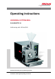
Operating instructions UNIVERSAL CUTTING MILL PULVERISETTE 19 Valid starting with: 19.
Fritsch GmbH Milling and Sizing Industriestraße 8 55743 Idar-Oberstein Telephone: +49 (0)6784/ 70-0 Fax: +49 (0)6784/ 70-11 email: info@fritsch.de Internet: www.fritsch.
Certifications and CE conformity Certifications and CE conformity Certification Fritsch GmbH has been certified by the TÜV-Zertifizierungsgemeinschaft e.V. An audit certified that Fritsch GmbH conforms to the requirements of the DIN EN ISO 9001:2008. CE Conformity The enclosed Conformity Declaration lists the guidelines the FRITSCH instrument conforms to, to be able to bear the CE mark.
Table of contents Table of contents 1 Basic structure............................................................................... 7 2 Safety information and use........................................................... 9 2.1 Requirements for the user..................................................... 9 2.2 Scope of application............................................................... 9 2.2.1 Operating principle........................................................... 10 2.
Table of contents 5 Initial start-up.............................................................................. 5.1 Before switching on for the first time.................................. 5.2 Switching on......................................................................... 5.3 Function check..................................................................... 5.4 Switching off........................................................................ 25 25 26 26 26 6 Using the device..............
Table of contents 13 Safety logbook............................................................................. 58 14 Index.............................................................................................
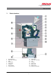
Basic structure 1 1 2 3 4 5 6 7 8 Basic structure Standard funnel Upper part of housing Rotor Fixed knife 1 Fixed knife 2 Closing lid Sieve cassette Collecting vessel 9 10 11 12 13 14 15 15* -7- Fixed knife 2 Lower part of housing Lock U-profile Latch clamp Motor cover Safety switch Safety switch bracket
Basic structure 1 14 18 19 20 21 Standard funnel Motor cover Ventilation grid Control switch Mains plug Funnel lid 22 23 24 26 34 35 -8- Protected funnel Plunger (protected funnel) Sample pusher Plunger (standard funnel) Start button Stop button
Safety information and use 2 Safety information and use 2.1 Requirements for the user This operating manual is intended for persons assigned with operating and monitoring the Fritsch PULVERISETTE 19. The operating manual and especially its safety instructions are to be observed by all persons working on or with this device. In addition, the applicable rules and regulations for accident prevention at the installation site are to be observed.
Safety information and use 2.2.1 Operating principle The material is fed through a funnel (example in image with standard funnel) into the cutting chamber. There, rotating knives (3) in combination with fixed knives (4,5,9) cut the material. The fine ground material falls through a sieve cassette (7) into the collecting vessel (8). For fine comminution, the sample exhaust system can be used with cyclone separator (optional accessory 45.5900.00). 2.
Safety information and use The applicable accident prevention guidelines must be complied with. Generally applicable legal and other obligatory regulations regarding environmental protection must be observed. 2.4 Information on hazards and symbols used in this manual Safety information Safety information in this manual is designated by symbols. Safety information is introduced by keywords that express the extent of the hazard.
Safety information and use DANGER! This symbol and keyword combination points out a directly hazardous situation due to electrical current. Ignoring information with this designation will result in serious or fatal injury. DANGER! This symbol and keyword combination designates contents and instructions for proper use of the machine in explosive areas or with explosive substances. Ignoring information with this designation will result in serious or fatal injury.
Safety information and use Example: 1. Loosen screw. 2. CAUTION! Risk of entrapment at the lid. Close the lid carefully. 3. Tighten screw. Tips and recommendations This symbol emphasises useful tips and recommendations as wells as information for efficient operation without mal‐ function.
Safety information and use CAUTION! Wear hearing protection! If a noise level of 85 dB(A) is reached or exceeded, ear protection should be worn to prevent hearing damage. WARNING! The maximum accepted concentration (MAC) levels of the relevant safety guidelines must be observed; if necessary, ventilation must be provided or the machine must be operated under an extractor hood. DANGER! Explosion hazard! – When Comminution oxidizable substances, e.g.
Safety information and use 2.6 Protective equipment n Protective equipment is to be used as intended and may not be disabled or removed. n All protective equipment is to be regularly checked for integrity and proper functioning. n The Universal Cutting Mill is equipped with a safety lock (11) which also protects the operator. This locks the front closing lid (6) during operation.
Safety information and use 3. At this time, it is not possible to switch on the Universal Cutting Mill. To switch it on, the safety lock (11) must be activated by turning the triangular key to the left, the closing lid (6) must be closed and the latch clamp (13) in locked position. 2.7 Hazardous points n The closing lid (6) can be lifted out of the hinges. When opening the upper part of the housing (2) it is possible to leave the closing lid (6) in the hinge.
Safety information and use n After checking if the rotor (3) is turning freely (Ä Chapter 6.1.7 ‘Checking if the rotor is turning freely’ on page 34), the required hexagon socket screw key must be removed immediately. 2.8 Electrical safety 2.8.1 General information n The switch (19) on the back is not a main switch but rather a control switch. Therefore the mains plug (20) must be plugged out in order to safely disconnect the supply voltage.
Technical data 3 Technical data 3.1 Dimensions 440 mm x 550 mm x 630 mm (width x depth x height) 3.2 Weight n 56 - 65 kg (net) n 86 - 95 kg (gross) 3.3 Operating noise The noise level is approx. 78 dB (A) when idle and 95 dB (A) when idle incl. cyclone separator. The value fluctuates strongly depending on the comminution material. 3.4 Voltage n 400V / 3~ n 230V / 1~ n 100-120V / 1~ 3.5 Current consumption n 16A for 400V / 3~ motor n 16A for 230V / 1~ motor n 15A for 100-120V / 1~ motor (Ä Chapter 4.
Technical data 3.7 Motor shaft power in accordance with VDE 0530, EN 60034 n n n n 2.2 kW for 400V / 3~ motor 1.5 kW for 400V / 3~ motor 1.5 kW for 230V / 1~ motor 1.1 kW for 100-120V / 1~ motor 3.8 Electrical fuses n Circuit breaker in device n Micro-fuse in device n Motor safety switch (Ä Chapter 6.4 ‘Overload of the cutting mill’ on page 37) n Direction of rotation detection in three-phase model (Ä Chapter 2.8 ‘Electrical safety’ on page 17) 3.
Installation 4 Installation 4.1 Transport n Transport on transport palette with a forklift or pallet truck. n When lifting the device hold it underneath at the back and front only. Do not lift it using the plastic cover. CAUTION! When lifting, at least 2 persons are required! 4.2 Unpacking n Pull out the nails that fasten the crate to the transport pallet. n Lift the crate off the transport pallet. n Compare the contents of the delivery with your order. 4.
Installation 4.5 Fastening the Universal Cutting Mill Screw the cutting mill tightly to the stand provided (acc. to instructions) or to a stable mount (table...). The following must be observed in order to fasten the device: n Unscrew the 3 screws fastening the motor cover (14). n Lift the motor cover (14) off carefully. n Two U-profiles (12) are mounted on the bottom of the device. Insert the 4 screws provided through the bore holes in the U-profiles (12) and screw them tightly to the stand or table.
Installation 4.6.2 Converting from standard funnel to protected funnel 1. Close the cutting mill. 2. Switch the control switch (19) on the back of the device to 0. 3. Remove the mains plug (20). 4. Unscrew the four M6x12 hexagon bolts fastening the standard funnel (1) to the upper part of the housing (2) using a hexagon socket screw key and lift off the standard funnel (1). 5. Insert the protected funnel (22) and fasten it with the four M6x12 hexagon bolts and the washers. 6.
Installation 3. Switch the control switch (19) on the back of the device to 0. 4. Remove the mains plug (20). 5. Unscrew the four M6x12 hexagon bolts fastening the protected funnel (22) to the upper part of the housing (2) using a hexagon socket screw key and lift off the protected funnel (22). 6. Insert the standard funnel (1) and fasten it with the four M6x12 hexagon bolts and the washers. 7. Connect the device again to the mains. 8.
Installation If the STOP button lights up red after connection to a three-phase power system and switching the control switch (19) to AUTO, the direction of rotation must be corrected. To do this, two phases in the mains plug must be reversed. DANGER! Changes to the connection line may only be made by a qualified person.
Initial start-up 5 Initial start-up 5.1 Before switching on for the first time 1. Connect the device to the mains with the mains plug (20). 2. Switch the control switch (19) on the back of the device to AUTO. The START button must light up green. If the STOP button lights up red, see Ä Chapter 4.7 ‘Electrical connection’ on page 23. 3. Switch the control switch (19) on the back of the device to AUTO. 4. Remove the cover cap (Z) of the central bore hole in the closing lid (6). 5.
Initial start-up 6. Remove the hexagon socket screw key again! 7. If the rotor (3) is not turning freely, proceed as described in Ä Chapter 6.1.3 ‘Setting the gap width of the knives’ on page 30. NOTICE! This check must also be carried out every time the rotor (3), the fixed knives (4, 5, 9) and the sieve cassette (7) are changed! 5.2 Switching on 1. Check again that the cutting mill is firmly fastened. 2. Check that the funnel (1, 22) is firmly mounted and closed. 3.
Initial start-up The switch (19) on the back is not a main switch but rather a control switch. Therefore the mains plug (20) must be plugged out in order to safely disconnect the supply voltage. CAUTION! Never unlock the latch clamp (13) during operation! Risk of severe and permanent damage to the rotor (3).
Using the device 6 Using the device 6.1 Preparing a comminution 6.1.1 Opening the cutting mill 1. Switch the control switch (19) on the back of the device to AUTO. 2. Unlock the latch clamp (13). 3. Open the closing lid (6). It is possible to lift the closing lid (6) out of the hinge after opening. However this is only necessary, for example, for cleaning. 4.
Using the device 6.1.2 6.1.2.1 Inserting / changing the fixed knives 1. Open the cutting mill (see Ä Chapter 6.1.1 ‘Opening the cutting mill’ on page 28) 2. When inserting or changing the fixed knives (4, 5, 9) the rotor (3) and the sieve cassette (7) must be removed (see Ä Chapter 6.1.4 ‘Inserting / changing a rotor’ on page 31 and Ä Chapter 6.1.5 ‘Inserting / changing a sieve cassette’ on page 33). 3. Loosen the retaining screws (A) to change or remove the fixed knives (4, 5, 9). 4.
Using the device 6.1.2.2 Installation position of the fixed knives with tungsten carbide cutting edge (9) Fixed knife 2 (4) Fixed knife 1 (5) Fixed knife 2 NOTICE! Observe the position of the strips of hardmetal tungsten carbide. These are marked in BLUE in the image above. 6.1.3 Setting the gap width of the knives The knife gap is set at the factory to approx. 0.2 mm. A B 1. Open the cutting mill (see Ä Chapter 6.1.
Using the device 4. Screw in the right and left threaded pins (B) beside the retaining screw (A) equally until the fixed knives (4, 5, 9) come up against the rotor knives. 5. Then turn the threaded pins (B) evenly back by ¼ of a turn and retighten the retaining screw (A). 6. Set all 3 fixed knives (4, 5, 9) in this way. A knife gap of approx. 0.2 mm is then set using this method. This can be checked using a feeler gauge. (0.2 mm, approx.
Using the device 1. Open the cutting mill (see Ä Chapter 6.1.1 ‘Opening the cutting mill’ on page 28). 2. Pull the rotor (3) forwards, wearing safety gloves. If the rotor (3) jams somewhat, lever it out carefully. 3. Clean the cone-shaped rotor holders (3). 4. Clean both cone-shaped holders (cones) in the closing lid (6) and on the holder. 5. Push the rotor (3) onto the rotor holder. Turn it clockwise until it engages in the 4 driving pins (C) on the back.
Using the device 6. Close the cutting mill (see Ä Chapter 6.1.6 ‘Closing the cutting mill’ on page 34). NOTICE! Check if the rotor (3) is turning freely (see Ä Chapter 6.1.7 ‘Checking if the rotor is turning freely’ on page 34). If this is not the case, proceed as described in Ä Chapter 6.1.3 ‘Setting the gap width of the knives’ on page 30. This check must also be carried out every time the rotor (3) is changed! 6.1.5 Inserting / changing a sieve cassette 1. Open the cutting mill (see Ä Chapter 6.1.
Using the device 6.1.6 6.1.7 Closing the cutting mill 1. Before closing the cutting mill, clean the cutting chamber, the contact surfaces of the housing and, in particular, the locking surfaces of the lock. 2. Swivel the upper part of the housing (2) slowly closed until it is resting on the lower part of the housing (10). 3. Close the closing lid (6). 4. Lock the latch clamp (13). 5. Switch the control switch (19) on the back of the device to HAND.
Using the device n Remove the hexagon socket screw key again immediately! n If the rotor (3) is not turning freely, proceed as described in Ä Chapter 6.1.3 ‘Setting the gap width of the knives’ on page 30. NOTICE! This check must also be carried out every time the rotor (3) and the fixed knives (4, 5, 9) are changed! 6.
Using the device 6.2.1 Using the plunger The plunger has 2 different sides for feeding the sample material in the funnel to the grinding chamber. On the one hand, the smooth, round side is suitable for finer material. On the other hand, the cross-shaped, thinner side is suitable for long, fibrous material, like straw. 6.3 Comminution procedure with the protected funnel 1. Switch the control switch (19) on the back of the device to AUTO. 2. Close the cutting mill (see Ä Chapter 6.1.
Using the device 10. Leave the sample pusher (24) down and move the plunger (23) downwards. ð The operating noise becomes louder. 11. Make pumping movements with the plunger (23). These pumping movements draw in and press out air through the blower filter above the collecting vessel. This air feeds the comminution material through the sieve or lifts it off the sieve and feeds it to the process again. 12. When the operating noise becomes quieter, the cutting procedure is complete.
Using the device 5. Lift the motor cover (14) off carefully. 6. Press the blue Reset switch. This must be set to "H". 7. Replace the motor cover (14) and screw it tight. 8. Connect the device again to the mains. 9. Switch the control switch (19) on the back of the device to AUTO. ð the Start button lights up green. The device is ready for operation.
Using the device 6.5 Sample exhaust system with cyclone separator CAUTION! Hearing damage! Wear hearing protection during sample extraction with the cyclone separator! (Optional accessory order number: 45.5900.00) The sample exhaust system with cyclone separator can be used for fine comminution. 27 28 29 30 31 32 33 1.
Using the device 2. Attach one end of the connection hose (28) with the rubber sleeve (29) to the adapter (27) and the other end to the cyclone separator (30). NOTICE! There are 2 opposing hose connections on the cyclone separator (30). Do not use the sealed connection; leave it closed. This would increase the noise level! 3. Close the cutting mill with mounted standard funnel (1) (see Ä Chapter 6.1.6 ‘Closing the cutting mill’ on page 34). 4.
Using the device The quantity of comminution material is based on the particle feed size and the grindability of the material. It is best to start with small quantities and increase them depending on the success of the comminution. NOTICE! When the sample bottle (32) is 2/3 full, stop the comminution. To do this, switch off the cutting mill (see Ä Chapter 5.4 ‘Switching off’ on page 26) and the sample exhaust system. Then empty the sample bottle (32).
Cleaning 7 Cleaning 7.1 Housing The cutting mill can be wiped down with a damp cloth when it is switched off. Disconnect the mains plug (20) from the electricity. DANGER! Do not allow any liquids to flow into the device. 7.2 Cutting chamber Clean the cutting chamber with a dust exhaust system and brush and also with compressed air, if necessary.
Cleaning 4. Slowly swivel open the upper part of the housing (2) with the closing lid (6) fully open, until it is resting on the rubber buffer. 5. Clean the cutting chamber. 7.3 Funnel Clean the funnels (1, 22) with a dust exhaust system and brush and also with compressed air, if necessary. 7.3.1 Standard funnel (1) 1. With the cutting chamber open, vacuum out the funnel from below 2. Clean the funnel from above.
Cleaning 7.3.2 Protected funnel (22) 1. Switch the control switch (19) on the back of the device to 0. 2. Pull the sample pusher (24) out of the protected funnel (22) until it stops and fasten it with knurled screw (A). 3. Open the funnel lid (21). 4. Clean the protected funnel (22) from above. 5. Close the funnel lid (21). 6. Pull the plunger (23) out of the protected funnel (22) until it stops and fasten it with knurled screw (B). 7. Open the cutting chamber as described above. 8.
Cleaning 7.3.2.2 Removing the plunger (23) 1. Open the funnel lid (21). 2. Unscrew the cross-head screws (D) with a screwdriver. 3. Close the funnel lid (21). 4. Unscrew the Torx screws (E) with a screwdriver. 5. Unscrew the knurled screw (B). 6. The plunger (23) can be taken out. 7. Install in reverse order. 7.4 Collecting vessel Pull out the collecting vessel (8) and clean it. It can be vacuumed or wiped down with a damp cloth.
Cleaning 7.5 Cleaning the sample exhaust system and cyclone separator The exhaust system can be disassembled and cleaned after opening the clips (F). To open and clean the cyclone separator, 4 screws in the inner part of the base must be loosened. 7.6 Cleaning the filter foam mat (B) 1. Vacuum the filter foam mat with the dust exhaust system 2. Subsequently wash it out with water. If necessary, you could use a tenside for cleaning. 3.
Maintenance 8 Maintenance 25 Exhaust filter A Filter holder B Filter foam mat NOTICE! Before starting maintenance work, that does not require mains voltage, unplug the mains plug (20) and protect the device against being unintentionally switched back on again! Indicate maintenance work with warning signs. The most important element of maintenance of the cutting mill is regular cleaning (Ä Chapter 7 ‘Cleaning’ on page 42).
Maintenance Function / Functional part Task Test Maintenance interval Exhaust filter (25) Filtering exhaust air Clean exhaust filter (25). To do this, lever out Before every commithe filter holder (A) with a screwdriver or nution similar. Beat the filter foam mat (B). Clean using compressed air or dust exhaust system. Replace the filter foam mat (B) if it is very heavily soiled. Article number: 90.0740.16 filter foam mat.
Maintenance - 49 -
Maintenance - 50 -
Repairs 9 Repairs DANGER! Mains voltage! – Before beginning with repair work, unplug the mains plug and protect the device against being unintentionally switched back on. – Indicate repair work with warning signs. – Repair work may only be performed by specialised personnel. – Put safety equipment back into operation after maintenance work. 9.
Repairs Fault description Cause Remedy Comminution material is escaping Material is extremely fine Insert sample exhaust system (see Ä Chapter 6.5 ‘Sample exhaust system with cyclone separator’ on page 39) Runs unevenly with strong vibrations Rotor imbalance Cones soiled (see Ä Chapter 6.1.4 ‘Inserting / changing a rotor’ on page 31) Bearing in closing lid (6) defective Replace bearing Pieces broken off rotor (3) Replace rotor (3) (Ä Chapter 6.1.
Disposal 10 Disposal It is hereby confirmed that FRITSCH has implemented the directive 2002/95/EC of the European Parliament and Council from 27th January 2003 for the limitation of the use of certain dangerous substances in electrical and electronic devices.
Guarantee terms 11 Guarantee terms Guarantee period As manufacturer, FRITSCH GmbH provides – above and beyond any guarantee claims against the seller – a guaranty valid for the duration of two years from the date of issue of the guarantee certificate supplied with the device. Within this guarantee period, we shall remedy all deficiencies due to material or manufacturing defects free of charge. Rectification may take the form of either repair or replacement of the device, at our sole discretion.
Guarantee terms Costs not covered by the guarantee This guarantee excludes any costs for transport, packaging or travel that accrue in the event the product must be sent to us or in the event that one of our specialist technicians is required to come to your site. Any servicing done by persons not authorised by us and any use of parts that are not original FRITSCH accessories and spare parts will void the guarantee.
Exclusion of liability 12 Exclusion of liability Before using the product, be sure to have read and understood this operating manual. The use of the product requires technical knowledge; only commercial use is permitted. The product may be used exclusively within the scope of applications set down in this operating manual and within the framework of guidelines put forth in this operating manual and must be subject to regular maintenance.
Exclusion of liability Fritsch GmbH excludes any liability, warranty, or other obligation to compensate for damages, regardless of whether this liability, warranty, or other obligation is explicit or implicit, contractual or arising from unlawful acts or prescribed contractually, by law, or otherwise.
Safety logbook 13 Date Safety logbook Maintenance / Repair Name - 58 - Signature
Safety logbook Date Maintenance / Repair Name - 59 - Signature
Index 14 Index A M Accident prevention . . . . . . . . . . . . . . . . . . . . . . . . 9 Authorised persons . . . . . . . . . . . . . . . . . . . . . . . . 9 Mains voltage . . . . . . . . . . . . . . . . . . . . . . . . . Maintenance . . . . . . . . . . . . . . . . . . . . . . . . . . Materials . . . . . . . . . . . . . . . . . . . . . . . . . . . . Motor shaft power . . . . . . . . . . . . . . . . . . . . . . B Basic structure . . . . . . . . . . . . . . . . . . . . . . . . . . . .
© 2014 Fritsch GmbH Milling and Sizing Industriestraße 8 55743 Idar-Oberstein Telephone: +49 (0)6784/ 70-0 Fax: +49 (0)6784/ 70-11 email: info@fritsch.de Internet: www.fritsch.