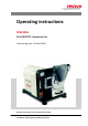
Operating instructions DISK MILL PULVERISETTE 13 premium line Valid starting with: 13.
Fritsch GmbH Milling and Sizing Industriestraße 8 55743 Idar-Oberstein Telephone: +49 (0)6784/ 70-0 Fax: +49 (0)6784/70-11 email: info@fritsch.de Internet: www.fritsch.
Certifications and CE conformity Certifications and CE conformity Certification Fritsch GmbH has been certified by the TÜV-Zertifizierungsgemeinschaft e.V. An audit certified that Fritsch GmbH conforms to the requirements of the DIN EN ISO 9001:2008. CE Conformity The enclosed Conformity Declaration lists the guidelines the FRITSCH instrument conforms to, to be able to bear the CE mark.
Table of contents Table of contents 1 Basic structure............................................................................... 6 2 Safety information and use........................................................... 7 2.1 Requirements for the user..................................................... 7 2.2 Scope of application............................................................... 7 2.2.1 Operating principle............................................................. 8 2.
Table of contents 6.8 6.9 6.10 6.11 Grinding with grinding disks of zirconium oxide.................. Adding material.................................................................... Taking samples................................................................... Final fineness..................................................................... 29 31 32 32 Accessories................................................................................... 7.1 Dust extraction..............................
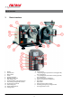
Basic structure 1 1 2 3 4 5 6 7 8 9 10 11 12 13 Basic structure Display Control panel Mains switch Funnel Fixed grinding disk Movable grinding disk Gap setting screw Grinding chamber closing mechanism Lock pin for grinding stock container Grinding stock container Suction flange lid Height-adjustable foot Locking switch 14 Housing cover a + key (changing the parameters and the gap width, menu navigation) b - key (changing the parameters and the gap width, menu navigation) c Up arrow key (menu navigation
Safety information and use 2 Safety information and use 2.1 Requirements for the user This operating manual is intended for persons assigned with operating and monitoring the Fritsch the PULVERISETTE 13 premium line. The operating manual and especially its safety instructions are to be observed by all persons working on or with this device. In addition, the applicable rules and regulations for accident prevention at the installation site are to be observed.
Safety information and use The material throughput of the disk mill lies in the range of 20 to 150 kg/ h. This depends on the setting of the output gap as well as the bulk weight and the comminution characteristics of the sample. 2.2.1 Operating principle The comminution of the material sample is done in a grinding chamber, which is sealed dust-proof to the outside, in which two roughly meshed grinding disks work against each other.
Safety information and use Neither compliance with this manual nor the conditions and methods used during installation, operation, use and maintenance of the the PULVERISETTE 13 premium line can be monitored by Fritsch GmbH. Improper execution of the installation can result in property damage and thus endanger persons.
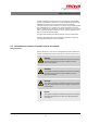
Safety information and use ENVIRONMENT! This symbol and keyword combination points out a possibly hazardous situation that can result in environmental damage if not avoided. Special safety information To call attention to specific hazards, the following symbols are used in the safety information: DANGER! This symbol and keyword combination points out a directly hazardous situation due to electrical current. Ignoring information with this designation will result in serious or fatal injury.
Safety information and use Safety information in the procedure instructions Safety information can refer to specific, individual procedure instructions. Such safety information is embedded in the procedure instructions so that the text can be read without interruption as the procedure is being carried out. The keywords described above are used. Example: 1. Loosen screw. 2. CAUTION! Risk of entrapment at the lid. Close the lid carefully. 3. Tighten screw.
Safety information and use 2.5 Device safety information Please observe! n Only use original accessories and original spare parts. Failure to observe this instruction can compromise the safety of the machine. n Accident-proof conduct is to be strictly followed during all work. n Comply with all currently applicable national and international accident prevention guidelines.
Safety information and use n Unauthorised alteration of the the PULVERISETTE 13 premium line will void Fritsch's declaration of conformity to European directives and void the guarantee. n Only use the the PULVERISETTE 13 premium line when it is in proper working order, as intended and in a safety- and hazard-conscious manner adhering to the operating manual. In particular, immediately rectify any malfunctions that could pose a safety hazard.
Safety information and use 3. A second protective device checks whether the grinding chamber has been closed by a motorized locking mechanism. 4. The locking switch (13) pulls in the grinding stock container after grinding starts and locks it with the lock pin that is attached to the container (9). The locking switch monitors whether the device has been properly closed during operation. It also prevents a start-up when the disk mill is open.
Safety information and use 2.8.2 Protection against restart The device shuts down if there is a power outage. n The mill comes to a standstill within seconds. n Grinding stock container can only be opened by an emergency release (k) on the inside of the device. For that, the housing cover (14) needs to be removed as follows. (See also Ä Chapter 4.3 ‘Set‐ ting up’ on page 18). – Open the housing cover (14) by releasing the quick release screws attached on both sides.
Technical data 3 Technical data 3.1 Dimensions 52 x 105 x 63 cm (width x depth x height) 3.2 Weight 228 kg without grinding disks (net) 246 kg with grinding disks made of tungsten carbide 3.3 Operating noise Emissions value of workplace according to DIN EN ISO 3746:2005 LPa = 68.9 dB(A). The noise level measurement was conducted with the grinding stock: sand, grain size 0.5 - 2mm. 3.4 Voltage, current consumption, power consumption Voltage 400V / 3~ 50Hz 230V / 3~ 60Hz Current consumption 3.
Technical data 3.7 Final fineness The final fineness lies between 0.05 and 12 mm.
Installation 4 Installation 4.1 Transport The device is delivered on a transport pallet with a wooden cover. We recommend using a forklift or pallet truck for transporting the packed device. DANGER! Do not step under the transport pallet during transport. WARNING! Improper lifting can lead to personal injury or property damage. The machine is only to be lifted with suitable equipment and by qualified personnel. The guarantee excludes all claims for damage due to improper transport. 4.
Installation To set up the disk mill, you need a crane or a different suitable transport device as well as 2 harnesses (not included in the scope of delivery) that are at least 40 cm long and have a capacity of 500 kg. CAUTION! The weight of the disk mill is approx. 260 kg with grinding disk and transport palette. NOTICE! Place the disk mill on a flat, stable surface. It may be screwed to this or a base plate. 1. The disk mill is screwed from below to the transport palette using 3 screws.
Installation 5. Lash the harness to a crane or another hoist. 6. Next lash the harness to the two eyelets provided for this. 7. Using the crane, bring the disk mill to the desired position. Make sure the device does not swing while it is being transported. 8. Remove the harness. 9. Replace the housing cover (14) and screw it tight. 4.4 Ambient conditions WARNING! Mains voltage! – The device may only be operated indoors. – The surrounding air may not carry any electrically conductive dust.
Installation 4.5.1 Adapting to the mains The PULVERISETTE 13 premium line is delivered with a connection voltage adapted to the electrical system of your country.
Initial start-up 5 Initial start-up The disk mill is delivered with a mounted grinding disk. Check the gap width before the first grinding. (See Ä Chapter 6.4 ‘Setting the gap width’ on page 27). After the disk mill has been set up as described in Ä Chapter 4.3 ‘Setting up’ on page 18 and the mains plug has been plugged into the mains socket, the device is ready for operation. Switch on the device only after all work described from Ä Chapter 4 ‘Installation’ on page 18 has been carried out.
Using the device 6 Using the device WARNING! If the grinding elements used are not original accessories, we provide no guarantee and exclude all liability for damage to the device. WARNING! Make sure before starting the machine that the grinding disks have been mounted properly and that there are not any loose parts inside the device. Failure to observe this provision will void the guarantee and releases us from liability for any resulting damage to the device or personal injury.
Using the device 6.1 Control panel n When the grinding chamber is open, the button (h) for locking the grinding chamber is not lit. n The button (h) flashes green as the grinding chamber closes by motor, and continues flashing until it is closed. Then it stays lit green. n During the start-up, the Start button (e) flashes green. Once the device is running, it stays lit green. n When the device is stopped, the Stop button (f) flashes until the wheel has come to a standstill. At standstill, it is lit red.
Using the device Menu change Selecting the menu items 1. To switch from the "Parameter" menu to the "Check/Setup" menu, press the arrow keys (c,d) until the - and + symbols on the bottom right of the display have a black background. Switch to the Check/Setup menu then by pressing the keys + (a) or - (b). 2. The menu change from the Check/Setup menu to the Parameter menu is done in the same manner. The menu items within the menus are selected by using the arrow keys (c,d). 6.
Using the device 1. To switch from the "Parameter" menu to the "Check/Setup" menu, press the arrow keys (c,d) until the - and + symbols on the bottom right of the display have a black background. Switch to the Check/Setup menu then by pressing the keys + (a) or - (b). 2. Close the grinding chamber and take out the grinding stock container. 3. To change the grinding gap for setting the zero point, the zero point line in the Check/Setup menu needs to be selected with the arrow keys (c,d) 4.
Using the device 6. Once the smallest gap width has been set and a minimal friction of the disks can be felt, this can be defined as the zero point. Only when the zero point has a black background, can the zero point be set by pressing the Stop (f) - and + (a) keys simultaneously. 7. Put the grinding stock container back in. 6.4 Setting the gap width Setting the gap width is done automatically in the Parameter menu item. First the zero point needs to be set (see Ä Chapter 6.
Using the device NOTICE! Grinding disks are worn down during grinding. That is why the grinding gap needs to be checked and readjusted if necessary depending on the use and the degree of wear. This is done as described in Ä Chapter 6.3 ‘Setting the zero point’ on page 25 andÄ Chapter 6.4 ‘Setting the gap width’ on page 27. 6.5 Revers mode If the grinding disks are worn on one side, the Revers mode can be selected. 1.
Using the device 6.6 Setting the grinding time 1. To switch from the "Check/Setup" menu to the "Parameter" menu, press the arrow keys (c,d) until the - and + symbols on the bottom right of the display have a black background. Switch to the Parameter menu then by pressing the keys + (a) or - (b). 2. Select the Timer menu item by pressing the arrow keys (c,d) and then set with the +/- key.
Using the device 1. Precise setting of the zero gap. The disks may under no circumstances touch each other during the grinding. The local heating promptly causes tension fissures at the circumference. These fissures appear very quickly and are easily detected. 2. Local heating can also occur if you fill in so much material that a comminution of a bed of material takes place constantly on the outer edges of the grinding disk (grinding gap completely filled with sample material).
Using the device 6.9 Adding material DANGER! Explosion hazard! – When grinding oxidisable substances, e.g. metal or coal, there is a risk of spontaneous combustion (dust explosion) if the proportion of fine particles exceeds a certain percentage. When grinding these kinds of substances, special safety measures must be taken and the work must be supervised by a specialist. – The device is not explosion-protected and is not suitable for grinding explosive materials.
Using the device 6.10 4. To close the lid, you have to press the pins on the quick closer into the grooves on the funnel and lock it by a quarter turn clockwise. 5. Observe the grinding process (grinding sound) and determine the optimal filled in quantity. Repeat this for each new material. 6. Do not refill more material until the grinding sound has lowered. 7. Maximum fed in quantity depends on the grindability of the material and the collecting volume of the grinding stock container. 8.
Accessories 7 Accessories 7.1 Dust extraction n 43.9050.00 Dust exhaust system, dust category "M" (43.9060.00 Dust exhaust system, dust category "H") n 43.9051.00 Polyester filter set (pack of 2) n 43.9052.00 Plastic bag (pack of 5) n 43.9055.00 Paper filter bag (pack of 5) Dust extraction attachment DANGER! Mains voltage! The mains plug needs to be disconnected before assembly begins. The assembly work may be carried out only by authorised personnel. 1.
Accessories 3. Insert the adapter (order no. 13.3250.00) for the dust extraction onto the exposed opening of the grinding chamber and fixate with the threaded pins. ð Place the exhaust hose onto the opening. 4. Connect the control box (86.5500.00) on the back side of thedisk mill with the connection cable (22.1870.00) to the exhaust connection. 5. Afterwards, plug the mains plug of dust extraction into the control box and the mains plug of the control box into the socket. 6.
Accessories 7.2 Dosed sample feeding with the LABORETTE 24 vibratory feeder To ensure a steady dosed feeding in of the sample material, you can employ the LABORETTE 24 vibratory feeder in combination with the PULVERISETTE 13 premium line . The feeder can be attached over the feeder connection on the disk mill's back side. During grinding, it feeds the sample material automatically to the device.
Cleaning 8 Cleaning DANGER! Mains voltage! – Before beginning with cleaning work, disconnect the mains plug and protect the device against being unintentionally switched back on! – Do not allow any liquids to flow into the device. – Indicate cleaning work with warning signs. – Put safety equipment back into operation after cleaning work. NOTICE! The grinding disk holder and the housing are made of spheroidal graphite cast iron. This steel cast is not stainless.
Cleaning WARNING! Danger of poisoning and fire! When using flammable or noxious cleansers, be sure to observe the valid safety regulations (MAK values) and clean the disk mill in a well-ventilated safety area if necessary. 8.3 Housing The outside of the machine can be cleaned with a soft, damp cloth when it is in the switched off state. A solution of water and a mild detergent can be used for that. Do not use solvents for cleaning. 8.
Maintenance 9 Maintenance DANGER! Mains voltage – Before beginning with maintenance work, unplug the mains plug and protect the device against being unintentionally switched back on again! – Indicate maintenance work with warning signs. – Maintenance work may only be performed by specialised personnel. – Put safety equipment back into operation after maintenance or repair work We recommend keeping a safety logbook Ä Chapter 15 ‘Safety logbook’ on page 54, where all work (maintenance, repairs......
Maintenance 9.1 Grinding disks The grinding disks wear down after a certain time, depending on the material being crushed. Check their surfaces in regular intervals. For changing the direction of rotation or exchanging the disks, observe the information in Ä Chapter 6.5 ‘Revers mode’ on page 28 and as follows in Ä Chapter 9.2 ‘Exchanging the grinding disks (5 + 6)’ on page 39. 9.
Maintenance NOTICE! Hold the grinding disks firmly during the exchange and do not drop them. This can cause disks made of zirconium oxide to break or splinter. Tools needed: n n n n Size 30 socket with locking handle (T and K) Locking spanner (B) M30 spanner (R) Hexagon socket set (I) DANGER! Make sure that the mains plug is disconnected from the mains after step 6. 1. Connect the device to the mains. 2. Switch main switch (3) to I (ON). 3.
Maintenance 5. The grinding chamber lock (8) is released. Open the grinding chamber now. The grinding disks become visible. The movable grinding disk (6) is fastened to the back with 2x M30 hexagon screws. 6. Switch the device off at the main switch (0). DANGER! Disconnect the mains plug from the mains and secure the device against being unintentionally switched back on. 7. Then use the locking spanner (B) to secure the support disk of the movable grinding disk.
Maintenance 9. The funnel (4) needs to be removed so that the fixed grinding disk (5) can be dismantled. 10. For this, remove the 3 marked cylinder screws. 11. Take the funnel off towards the front by tugging it. ð The fastening screws of the fixed grinding disk become visible. 12. CAUTION! Crushing hazard when exchanging the grinding disks. Make sure that the grinding disk does not fall on the floor. Loosen the 2x M30 fastening screws using the locking handle (K). Hold the grinding disk firm.
Maintenance 16. Open the grinding chamber and slide the locking spanner as far as possible through the hinge of the grinding chamber. Depending on the wear on the old grinding disks, the position of the retracted movable grinding disk may mean that the locking spanner will not fit behind it any more. From point 14, positioning behind the mov‐ able grinding disk is no longer necessary.
Maintenance Material Reference Density g/cm³ value for max. tightening torque (Nm) Abrasion resistance Use for material to be crushed Order number Order number fixed disk: movable disk: Tungsten carbide 90.3% WC + 9.5% Co at least 50 14,8 Very good Hard, abrasive sample material 13.2000.08 13.2010.08 Zirconium oxide 94.5 % ZrO2 approx. 20 6,0 Extremely good Medium-hard, abrasive sample material for ironfree grinding 13.2100.27 13.2110.27 9.
Maintenance 4. Remove the motor fastening screw (m) under the oil drain screw (n) with a hexagon socket screw key M10. There is about 0.22 litres of ISO VG 220 gear oil in the gears. 5. Hold a flat container under the oil drain screw (n) and unscrew it with a no. 5 hexagon socket screw key until oil flows out. 6. Allow the oil to drain from the gears completely (about 0.22 L).
Repairs 10 Repairs DANGER! Mains voltage! – Before beginning with repair work, unplug the mains plug and protect the device against being unintentionally switched back on. – Indicate repair work with warning signs. – Repair work may only be performed by specialised personnel. – Put safety equipment back into operation after maintenance work. 10.
Repairs Malfunction Grinding stock escapes Possible cause Rectify fault Grinding disks not installed parallel Dismantle grinding disks, clean holder and install again (See Ä Chapter 6 ‘Using the device’ on page 23) Grinding chamber and grinding stock container seals are soiled or defective Clean or replace seals Collecting container overflow (max.
Examples of comminution tasks 11 Examples of comminution tasks n Particle feed size 20 mm n Feed quantity 1 kg n Material sorted from hard to medium-hard Grinding stock Grinding duration (min.
Disposal 12 Disposal It is hereby confirmed that FRITSCH has implemented the directive 2002/95/EC of the European Parliament and Council from 27th January 2003 for the limitation of the use of certain dangerous substances in electrical and electronic devices.
Guarantee terms 13 Guarantee terms Guarantee period As manufacturer, FRITSCH GmbH provides – above and beyond any guarantee claims against the seller – a guaranty valid for the duration of two years from the date of issue of the guarantee certificate supplied with the device. Within this guarantee period, we shall remedy all deficiencies due to material or manufacturing defects free of charge. Rectification may take the form of either repair or replacement of the device, at our sole discretion.
Guarantee terms Costs not covered by the guarantee This guarantee excludes any costs for transport, packaging or travel that accrue in the event the product must be sent to us or in the event that one of our specialist technicians is required to come to your site. Any servicing done by persons not authorised by us and any use of parts that are not original FRITSCH accessories and spare parts will void the guarantee.
Exclusion of liability 14 Exclusion of liability Before using the product, be sure to have read and understood this operating manual. The use of the product requires technical knowledge; only commercial use is permitted. The product may be used exclusively within the scope of applications set down in this operating manual and within the framework of guidelines put forth in this operating manual and must be subject to regular maintenance.
Exclusion of liability Fritsch GmbH excludes any liability, warranty, or other obligation to compensate for damages, regardless of whether this liability, warranty, or other obligation is explicit or implicit, contractual or arising from unlawful acts or prescribed contractually, by law, or otherwise.
Safety logbook 15 Date Safety logbook Maintenance / Repair Name - 54 - Signature
Safety logbook Date Maintenance / Repair Name - 55 - Signature
Safety logbook Date Maintenance / Repair Name - 56 - Signature
Safety logbook Date Maintenance / Repair Name - 57 - Signature
Index 16 Index A M Accident prevention . . . . . . . . . . . . . . . . . . . . . . . . 7 Adding material . . . . . . . . . . . . . . . . . . . . . . . . . . 31 Ambient conditions . . . . . . . . . . . . . . . . . . . . . . . 20 Authorised persons . . . . . . . . . . . . . . . . . . . . . . . . 7 Mains adaptation . . . . . . . . . . . . . . . . . . . . . . . Maintenance . . . . . . . . . . . . . . . . . . . . . . . . . . Menu change . . . . . . . . . . . . . . . . . . . . . . . . . Menu navigation . .
© 2014 Fritsch GmbH Milling and Sizing Industriestraße 8 55743 Idar-Oberstein Telephone: +49 (0)6784/ 70-0 Fax: +49 (0)6784/70-11 email: info@fritsch.de Internet: www.fritsch.