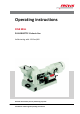
Operating instructions DISK MILL PULVERISETTE 13 classic line Valid starting with: 13.
Fritsch GmbH Milling and Sizing Industriestraße 8 D - 55743 Idar-Oberstein Telephone: +49 (0)6784/ 70-0 Fax: +49 (0)6784/ 70-11 email: info@fritsch.de Internet: www.fritsch.
Certifications and CE conformity Certifications and CE conformity Certification Fritsch GmbH has been certified by the TÜV-Zertifizierungsgemeinschaft e.V. An audit certified that Fritsch GmbH conforms to the requirements of the DIN EN ISO 9001:2008. CE Conformity The enclosed Conformity Declaration lists the guidelines the FRITSCH instrument conforms to, to be able to bear the CE mark.
Table of contents Table of contents 1 Basic structure............................................................................... 6 2 Safety information and use........................................................... 7 2.1 Requirements for the user..................................................... 7 2.2 Scope of application............................................................... 7 2.2.1 Operating principle............................................................. 8 2.2.2 Drive motor..
Table of contents 6.4 Adding material.................................................................... 25 6.5 Taking samples..................................................................... 26 6.6 Final fineness....................................................................... 26 7 Accessories................................................................................... 27 7.1 Dust extraction..................................................................... 27 7.
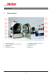
Basic structure 1 1 2 3 4 5 Basic structure Funnel with funnel lid Cover for dust extraction / gap adjustment Fixed grinding disk Safety switch Grinding stock container 6 7 8 9 10 -6- Grinding stock container safety switch Movable grinding disk Coupling cover Latch Main switch
Safety information and use 2 Safety information and use 2.1 Requirements for the user This operating manual is intended for persons assigned with operating and monitoring the Fritsch PULVERISETTE 13 classic line. The operating manual and especially its safety instructions are to be observed by all persons working on or with this device. In addition, the applicable rules and regulations for accident prevention at the installation site are to be observed.
Safety information and use The material throughput of the disk mill lies in the range of 20 to 150 kg/ h. This depends on the setting of the output gap as well as the bulk weight and the comminution characteristics of the sample. 2.2.1 Operating principle The comminution of the material sample is done in a grinding chamber, which is sealed dust-proof to the outside, in which two roughly meshed grinding disks work against each other.
Safety information and use By using the PULVERISETTE 13 classic line the customer agrees with this and recognizes that defects, malfunctions or errors cannot be completely excluded. To prevent risk of damage to persons or property or of other direct or indirect damage, resulting from this or other causes, the customer must implement sufficient and comprehensive safety measures for working with the PULVERISETTE 13 classic line.
Safety information and use NOTICE! This symbol and keyword combination points out a possibly hazardous situation that can result in property damage if not avoided. ENVIRONMENT! This symbol and keyword combination points out a possibly hazardous situation that can result in environmental damage if not avoided.
Safety information and use WARNING! This symbol and keyword combination points out a directly hazardous situation due to hot surfaces. Ignoring information with this designation can result in serious burn injuries due to skin contact with hot surfaces. Safety information in the procedure instructions Safety information can refer to specific, individual procedure instructions.
Safety information and use Designation Explanation [Button] Operating elements (e.g. push button, switch), display elements (e.g. signal lamps) ‘Display’ Screen elements (e.g. buttons, function key assignment) 2.5 Device safety information Please observe! n Only use original accessories and original spare parts. Failure to observe this instruction can compromise the safety of the machine. n Accident-proof conduct is to be strictly followed during all work.
Safety information and use n Unauthorised alteration of the PULVERISETTE 13 classic line will void Fritsch's declaration of conformity to European directives and void the guarantee. n Only use the PULVERISETTE 13 classic line when it is in proper working order, as intended and in a safety- and hazard-conscious manner adhering to the operating manual. In particular, immediately rectify any malfunctions that could pose a safety hazard.
Safety information and use 2.7 Hazardous points CAUTION! – Crushing hazard at the funnel cover (1). – Crushing hazard at the grinding chamber latch (9). 2.8 Electrical safety 2.8.1 General information The disk mill is switched on and off with a motor protection switch that is adapted to the mains voltage (according to the type plate). n By turning the switch to Start (I): ® the disk mill starts up n By turning the switch to Stop (O): ® the mill comes to a standstill within approx.
Technical data 3 Technical data 3.1 Dimensions 400 x 440 x 870 mm (height x width x depth) 3.2 Weight 140 kg without grinding disks (net) 160 kg with grinding disks made of tungsten carbide 3.3 Operating noise Emissions value of workplace according to DIN EN ISO 3746:2005 LPa = 81 dB(A). 3.4 Voltage n 400 V / 3~ 50 Hz n 230 V / 3~ 60 Hz 3.5 Current consumption n 3.2 A at 400 V / 3~ 50 Hz n 5.6 A at 230 V / 3~ 60 Hz 3.
Technical data 3.8 Electrical fuses A thermal circuit breaker (motor protection switch) is integrated into the main switch (10) and triggers in the event of overheating; after a brief cooling period, it is ready to be restarted. 3.9 Material n Maximum feeding size approx. 20 mm (depending on the material) n Minimum feed quantity 20 - 30 ml n Grinding by batches with grinding stock container (max. 2 l container volume) n Maximum throughput 150 kg/h during continuous grinding 3.
Installation 4 Installation 4.1 Transport The device is delivered on a transport pallet with a wooden cover. We recommend using a forklift or pallet truck for transporting the packed device. DANGER! Do not step under the transport pallet during transport. WARNING! Improper lifting can lead to personal injury or property damage. The machine is only to be lifted with suitable equipment and by qualified personnel. The guarantee excludes all claims for damage due to improper transport. 4.
Installation CAUTION! The weight of the disk mill is approx. 160 kg with grinding disks. NOTICE! Place the disk mill on a flat, stable surface. It may be screwed to this or a base plate. 1. The disk mill is screwed to the transport palette from below using 3 screws. Loosen the screws with a spanner (17 mm). 2. Lash the harness to a crane or another hoist. 3. Next lash the harness to the eyelets. 4. Using the crane, bring the disk mill to the desired position.
Installation CAUTION! Ignoring the values on the type plate may result in damage to the electrical and mechanical components. 4.5.1 Adapting to the mains The disk mill is delivered with a connection voltage adapted to the electrical system of your country.
Initial start-up 5 Initial start-up The disk mill is delivered with mounted grinding disks. Check the gap width before the first grinding. (See Ä Chapter 6.2 ‘Setting the gap width’ on page 23). After the disk mill has been set up as described in Ä Chapter 4 ‘Installation’ on page 17 and the mains plug has been plugged into the mains socket, the device is ready for operation. CAUTION! – Grinding disks must not touch each other.
Using the device 6 Using the device WARNING! If the grinding elements used are not original accessories, we provide no guarantee and exclude all liability for damage to the device. WARNING! Make sure before starting the machine that the grinding disks have been mounted properly and that there are not any loose parts inside the device. Failure to observe this provision will void the guarantee and releases us from liability for any resulting damage to the device or personal injury.
Using the device 6.1 Setting the minimum gap width The minimum gap width is limited to 0.1 mm in the condi‐ tion of delivery. A stop screw with lock nut is located at the back left of the sliding table, which limits the forward movement of the sliding table. This prevents the grinding disks from touching inadvertently. The minimum gap width has to be reset after every change or prolonged use of the grinding disks. Grinding disks may have different thicknesses depending on the wear.
Using the device 4. With a feeler gauge (if unavailable normal printer paper that has been folded once can also be used), set the gap to 0.1 mm using the rotary handle. This is set through a viewing gap above the grinding chamber (2). The feeler gauge can be inserted through the opening to set or check the gap width. The feeler gauge must only be lightly clamped and it must be possible to pull it out again by hand without any problems. 5.
Using the device 6.3 Grinding with grinding disks of zirconium oxide When grinding with zirconium oxide grinding disks, certain work precautions need to be observed: 1. Precise setting of the smallest gap. The disks may under no circumstances touch each other during the grinding. The local heating promptly causes tension fissures at the circumference. These fissures appear very quickly and are easily detected. 2.
Using the device 6.4 Adding material DANGER! Explosion hazard! – When grinding oxidisable substances, e.g. metal or coal, there is a risk of spontaneous combustion (dust explosion) if the proportion of fine particles exceeds a certain percentage. When grinding these kinds of substances, special safety measures must be taken and the work must be supervised by a specialist. – The device is not explosion-protected and is not suitable for grinding explosive materials.
Using the device 6.5 Taking samples Depending on the quantity of the ground material, be sure to use both hands when taking out the grinding stock con‐ tainer. Hazard of tipping! 6.6 Final fineness The final fineness that can be achieved depends on the selected gap width (approx. 0.1 mm to approx. 12 mm). The gap width determines just one dimension of the individual particles in the fine ground material.
Accessories 7 Accessories 7.1 Dust extraction n 43.9050.00 Dust exhaust system, dust category "M" (43.9060.00 Dust exhaust system, dust category "H") n 43.9051.00 Polyester filter set (pack of 2) n 43.9052.00 Plastic bag (pack of 5) n 43.9055.00 Paper filter bag (pack of 5) After a grinding process has ended, you can suck off the dust that has accumulated during grinding, by attaching the vacuum cleaner connection piece (order no.: 13.1450.
Accessories 7.2 Comminution of coarse material in combination with the Jaw Crusher PULVERISETTE 1 classic line The disk mill PULVERISETTE 13 classic line is used in combination with the Jaw Crusher PULVERISETTE 1 classic line for comminution of coarse material before its subsequent use. The comminution is done in this combination in a single pass with 95 mm (or 65 mm) feed size up to an average particle feed size (d50) of 0.1 mm. The jaw crusher is placed on a mounting rack (order no. 43.5100.
Cleaning 8 Cleaning DANGER! Mains voltage! – Before beginning with cleaning work, disconnect the mains plug and protect the device against being unintentionally switched back on! – Do not allow any liquids to flow into the device. – Indicate cleaning work with warning signs. – Put safety equipment back into operation after cleaning work. NOTICE! The grinding disk holder and the housing are made of spheroidal graphite cast iron. This steel cast is not stainless.
Cleaning WARNING! Danger of poisoning and fire! When using flammable or noxious cleansers, be sure to observe the valid safety regulations (MAK values) and clean the disk mill in a well-ventilated safety area if necessary. 8.3 Housing The outside of the machine can be cleaned with a soft, damp cloth when it is in the switched off state. A solution of water and a mild detergent can be used for that. Do not use solvents for cleaning.
Maintenance 9 Maintenance DANGER! Mains voltage – Before beginning with maintenance work, unplug the mains plug and protect the device against being unintentionally switched back on again! – Indicate maintenance work with warning signs. – Maintenance work may only be performed by specialised personnel. – Put safety equipment back into operation after maintenance or repair work We recommend keeping a safety logbook Ä Chapter 15 ‘Safety logbook’ on page 45, where all work (maintenance, repairs......
Maintenance Functional part Task Test Maintenance interval Protection switch 1 (activated by closing the grinding chamber) Start-up block Grinding chamber open: Mill does not start! Before each use (replace defective switch) Caution! If the switch is defective, the disks will start up. Do not reach into the mill while it is running.
Maintenance 9.1.1 Carrying out a gear oil exchange 1. Have the PULVERISETTE 13 classic line run for approx. 15 minutes so that the gear oil inside warms up and drains better. 2. Remove the coupling cover by unscrewing the fastening screws with a no. 4 hexagon socket screw key on both sides. 3. Take off the coupling cover. 4. Remove the motor fastening screw under the oil drain screw with a no. 6 hexagon socket screw key. 5.
Maintenance 10. After this, unscrew the filling screw with a no. 11 hexagon socket screw key. 11. Insert a funnel into the bore hole and fill the gears with 0.22 litre ISO VG 220 gear oil, (order no.: 85.0110.00). 12. Screw in the filling screw with the clean seal ring. 9.2 Rotation direction of the drive motor DANGER! Mains voltage! Changes to the rotation direction may only be made by a qualified technician. The rotation direction of the three-phase motor is user-defined.
Maintenance CAUTION! Clean the holder and the back of the disks thoroughly before installing the new disks. This is very important in particular when employing the ZrO2 and WC+Co disks, so that the disks are seated without tension and parallel to each other. When using the ZrO2 grinding disks: When tightening the screws, it is important that the tightening torque is not too great (see table) and is the same for both screws.
Maintenance 9.3.2 2. Open the grinding chamber. 3. Hold the fixed grinding disk tightly from the inside and remove the fastening screws or fastening nuts. 4. Remove the fixed grinding disk and clean the surfaces. Reverse the steps to insert the replacement grinding disk. Exchanging the movable grinding disks 1. Open the grinding chamber. 2. To be able to remove the fastening screws (fastening nuts for ZrO2) behind the movable grinding disk, this has to be moved far forward. 3.
Maintenance Material Reference Density g/cm³ value for max. tightening torque (Nm) Abrasion resistance Use for material to be crushed Order number Order number fixed disk: movable disk: Tempered steel cast 11-12% Cr at least 50 7,9 Good Hard, brittle sample material 13.1100.09 13.1110.09 Manganese steel 12-13% Mn at least 50 7,9 - 8 Good Hard, brittle sample material 13.1120.23 13.1130.23 Tungsten carbide 90.3% WC + 9.
Repairs 10 Repairs DANGER! Mains voltage! – Before beginning with repair work, unplug the mains plug and protect the device against being unintentionally switched back on. – Indicate repair work with warning signs. – Repair work may only be performed by specialised personnel. – Put safety equipment back into operation after maintenance work. 10.
Examples of grinding results 11 Examples of grinding results n Particle feed size 20 mm n Feed quantity 1 kg n Material sorted from hard to medium-hard Grinding stock Grinding duration (min.
Disposal 12 Disposal It is hereby confirmed that FRITSCH has implemented the directive 2002/95/EC of the European Parliament and Council from 27th January 2003 for the limitation of the use of certain dangerous substances in electrical and electronic devices.
Guarantee terms 13 Guarantee terms Guarantee period As manufacturer, FRITSCH GmbH provides – above and beyond any guarantee claims against the seller – a guaranty valid for the duration of two years from the date of issue of the guarantee certificate supplied with the device. Within this guarantee period, we shall remedy all deficiencies due to material or manufacturing defects free of charge. Rectification may take the form of either repair or replacement of the device, at our sole discretion.
Guarantee terms Costs not covered by the guarantee This guarantee excludes any costs for transport, packaging or travel that accrue in the event the product must be sent to us or in the event that one of our specialist technicians is required to come to your site. Any servicing done by persons not authorised by us and any use of parts that are not original FRITSCH accessories and spare parts will void the guarantee.
Exclusion of liability 14 Exclusion of liability Before using the product, be sure to have read and understood this operating manual. The use of the product requires technical knowledge; only commercial use is permitted. The product may be used exclusively within the scope of applications set down in this operating manual and within the framework of guidelines put forth in this operating manual and must be subject to regular maintenance.
Exclusion of liability Fritsch GmbH excludes any liability, warranty, or other obligation to compensate for damages, regardless of whether this liability, warranty, or other obligation is explicit or implicit, contractual or arising from unlawful acts or prescribed contractually, by law, or otherwise.
Safety logbook 15 Date Safety logbook Maintenance / Repair Name - 45 - Signature
Index 16 Index A O Accident prevention . . . . . . . . . . . . . . . . . . . . . . . . 7 Adapting to the mains . . . . . . . . . . . . . . . . . . . . . 19 Adding material . . . . . . . . . . . . . . . . . . . . . . . . . . 25 Ambient conditions . . . . . . . . . . . . . . . . . . . . . . . 18 Authorised persons . . . . . . . . . . . . . . . . . . . . . . . . 7 Operating noise . . . . . . . . . . . . . . . . . . . . . . . . . . 15 Overload protection . . . . . . . . . . . . . . . . . . . . . . .
© 2014 Fritsch GmbH Milling and Sizing Industriestraße 8 D - 55743 Idar-Oberstein Telephone: +49 (0)6784/ 70-0 Fax: +49 (0)6784/ 70-11 email: info@fritsch.de Internet: www.fritsch.