JAW CRUSHER Operating Manual Translation of the original FRITSCH JAW CRUSHER
Fritsch GmbH Milling and Sizing Industriestrasse 8 D - 55743 Idar-Oberstein Phone: Fax: E-Mail: Internet: +49 (0)6784/ 70-0 +49 (0)6784/ 70-11 info@fritsch.de http://www.fritsch.de Fritsch GmbH, has been certified by the TÜV-Zertifizierungsgemeinschaft e.V. Certificat registration number 71 100 J 596. It was verified through an audit that Fritsch GmbH satisfies the requirements of DIN EN ISO 9001:2008.
Table of contents page 1 Basic Design .........................................................................................4 2 Safety Instructions and Proper Use....................................................6 2.1 2.2 2.2.1 2.3 2.4 2.5 2.6 2.7 2.8 2.8.1 2.8.2 3 3.1 3.2 3.3 3.4 3.5 3.6 3.7 4 4.1 4.2 4.3 4.4 4.5 4.6 4.6.1 4.6.2 4.6.3 4.7 5 5.1 5.2 5.2.1 5.2.2 5.2.3 5.3 5.3.1 5.3.2 5.3.3 5.3.4 5.3.5 Requirements on the Operator .............................................................
6 6.1 6.1.1 6.2 6.2.1 6.2.2 6.2.3 6.2.3.1 6.2.3.2 6.2.3.3 6.3 7 7.1 7.2 8 8.1 8.2 8.3 Accessories ........................................................................................22 Dust extraction ............................................................................................ 22 Converting for dust extraction ............................................................................22 Conversion set for iron-free preliminary grinding ........................................
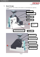
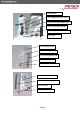
1 Basic Design The designations and numbering shown below are used throughout this operating manual.
(3) guide bolt (13) support wall (both sides) (14) crusher jaw movable cpl. (15) crusher jaw fixed cpl.
2 Safety Instructions and Proper Use 2.1 Requirements on the Operator This operating manual is intended for persons who are assigned the operation and supervision of Fritsch Jaw Crusher. Persons under the influence of health impairments, medications, drugs, alcohol or excessive fatigue may not operate the instrument. The instrument may only be operated by authorised persons and may only be maintained and repaired by trained experts.
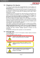
2.3 Obligations of the Operator This manual must be carefully read and understood before using the product. Use of the product requires specialised knowledge and may only be undertaken by commercial users. The operating personnel must be familiar with the contents of the operating manual. It is therefore very important that this operating manual also actually be provided to these persons. It must be ensured that this operating manual always remains alongside the instrument.
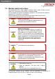
2.5 Machine safety instructions We recommend that a safety logbook should be kept in which all work (service, repairs etc.) carried out on the machine should be entered. Use only original accessories and original spare parts. The safety of the machine is impaired if this instruction is not followed. Operating personnel must always operate the machine with safety in mind. Do not run the laboratory jaw crusher unsupervised.
2.6 Safety equipment TIP Safety equipment must be used in accordance with the regulations and must not be rendered inoperative or be removed. All safety equipment must be checked regularly for completeness and function. Inside the jaw crusher „pulverisette 1“ several elements independently acting contribute to security: 1. Reaching into the funnel (1) is prevented by the zigzag-shaped material passageway. 2.
3 Technical Data 3.1 Dimensions Model I + II: 72 x 41 x 83 (Höhe x Breite x Tiefe) 3.2 Weight Model I: net 177 kg Model II: net 205 kg gross 202 kg gross 230 kg 3.3 Working noise The noise level equals up to approx. 93dB (A). 3.
4 Installation 4.1 Transportation CAUTION The weight of the laboratory jaw crusher is Model I: 177 kg Model II: 205 kg The laboratory jaw crusher is delivered on a transport pallet with a wooden cover. We recommend using a forklift or pallet truck to transport the packaged instrument. 4.2 Unpacking • Pull the staples out of the cover with a pulling tool (or pliers). • Lift it off the transport pallet with the help of a second person. • Compare the contents of the delivery with your order. 4.
2. Pull its free end through the two holes at the narrow side of the jaw crusher holes and fasten it at the rope in the same way you did first. 3. Do the same with a second rod and rope at the opposite side. 4. With the help of the iron rods 4 support people carry the jaw crusher; the fifth one prevent it from swinging during transport. • The jaw crusher must be placed on an even, stable surface. If you wish, you can also screw it to such a surface or to a ground plate. 4.
2. Lift off the rubber seal on the funnel opening of the jaw crusher. To do so, remove the 4 cylinder head screws with washers using the Allen key. 3. Pull the rubber seal over the funnel neck. Take note of the positions of the holes in the filling funnel and rubber seal. 4. Insert the filling funnel into the funnel opening on the top of the laboratory jaw crusher. 5. Screw the filling funnel onto the housing with the 4 previously removed cylinder head screws and washers. 6.
4.6 Electrical connection CAUTON Secure the electrical system! Danger of damage due to short-circuit. Make certain that the socket is connected to a mains line secured with a residual current circuit breaker. Kindly compare the tension and current values indicated on the sign with the values of the existing power supply system before connecting the instrument. (See chapter 3) 4.6.1 Matching the jaw crusher to the mains voltage DANGER 4.6.
4.7 Initial switch-on / performance check CAUTION Danger of crushing! Only start the jaw crusher with the funnel (1) attached! The machine may be switched on only after all work described in the chapter 4 on Installation has been carried out. During the first operating hours, it is possible that some grease may escape from the eccentric cam bearing of the movable crushing jaw (see also chapter 8.3).
Model II Material Name Order-No. tempered steel fixed crushing plate 43.3010.09 movable crushing plate 43.3020.09 1 pair of support walls 43.3070.09 fixed crushing plate 43.3030.10 movable crushing plate 43.3040.10 1 pair of support walls 43.3080.10 stainless steel Hard metal tungsten carbide fixed crushing plate zirconium oxide manganese steel 43.3050.08 movable crushing plate 43.3060.08 1 pair of support walls 43.3090.08 fixed crushing plate 43.3100.27 movable crushing plate 43.
5.2.1 Mounting the crushing plates TIP The crushing plates have different shapes. The fixed crushing plate (18) has plane parallel surfaces, the movable crushing plate (22) is convex on the crushing surface and it is a bit longer. CAUTION Crushing jaw (15) hold on tight! Part weighs about 6.5 kg To replace the fixed crushing plate (18), remove the guide bolt (3) and take out the crusher jaw (15).
5.2.2 Checking the gap (25) fly-wheel gap 0.5-1mm After installing the crushing plates (18, 22), you must check the gap between the plates: To do this, you must remove the belt guard outside (9). The fastening screws of the belt guard outside (9) are located under the edge protection (8). When the belt guard outside (9) is removed, the fly-wheel (25) can be turned by hand. Set the indexing cranked handle (7) to the lowest setting.
5.2.3 Mounting the support walls WARNING The fly-wheel (25) is very heavy. At least 2 people are required for disassembly. Replacing the lateral support walls (13) is practically only required if the material of the crushing plates (18. 22) is replaced by another one (i.e. from tool steel to stainless steel) and if even the smallest (P.P.M. range) contamination (abrasion) from the support walls has to be avoided. First lift out the fixed crusher jaw (17) as described in chapter 5.2.1.
5.3 Crushing of material 5.3.1 Setting the jaw gap The opening of the gap between the crusher plates determines the average grain size of the crushed material. With the indexing cranked handles (7) the opening gap can be selected by steps between about 1 mm and 15 mm. (In the lowest position the gap is the smallest). To select a different gap, pull out the knurled knob of the indexing cranked handles (7) and insert the indexing cranked handles into the desired position.
5.3.4 Final size The obtainable final size depends upon the selected gap setting (about 1 mm to 15 mm). The gap setting determines only one dimension of the crushed material. This means, that for instance flaky shaped material can have a completely different size in another dimension compared with the set gap. If this should be the case, in many cases a second pass of he crushed material through the crusher will considerably reduce the amount of the grains being larger in one dimension.
6 Accessories 6.1 Dust extraction • 43.9050.00 Dust extraction device • 43.9051.00 Polyester filter set (2-pack) • 43.9052.00 Plastic bag (5-pack) (a) Allen key (26) Rear cover (27) Cover dust extraction Der Labor-Backenbrecher wird ohne Absaugöffnung ausgeliefert. Um eine Staubabsaugvorrichtung benutzen zu können, muss die rear cover (26) durch eine spezielle cover dust extraction (27) ersetzt werden.
2. Pull up the rear cover (26) and slide the cover dust extraction (27) with the oblong holes onto the screws. Make certain that the washers are positioned under the screw heads. Screw in both upper screws and retighten the lower screws. c e f (84.4345.1 d 3. The following accessories are included with the dust extractor: Vacuum hose (c), reducing adapter (d) and 2 rubber collars of different sizes (e,f). The rubber collar 84.4345.15 (f) with the larger outside diameter is required. 4.
6.2 Conversion set for iron-free preliminary grinding 6.2.1 • • • • or • 01.5410.00 Funnel PVC incl. clamping block 43.0100.27 Fixed crushing plates of zirconium oxide 43.0110.27 Movable crushing plates of zirconium oxide 43.0160.27 pair supporting walls of zirconium oxide 43.0150.13 1 pair supporting walls of aluminium 6.2.2 • • • • or • Model I Model II 01.7410.00 Funnel PVC incl. clamping block 43.3100.27 Fixed crushing plates of zirconium oxide 43.3110.
Funnel (A) with safety switch 4x cylinder head screws M6x12 (E) 4x washers (F) 1x cylinder head screw M6x12 (G) 1x cable clamp (H) 1x angled screw coupling with thread PG11 (B) 1x angle screw coupling with thread M20 (D) 2x clamping blocks (C) of anodised aluminium Funnel fastener Cable conduit fastener (The standard for cable screw connections was changed during the manufacturing period of the device.) Crushing plate fastener 6.2.3.
2. Mount the funnel (A) in the position shown above with the 4 cylinder head screws M6x12 (E) and the 4 washers (F). PG11 or M20 ? Æ Check!! 3. Select the angled screw coupling (B or D) with the correct thread (PG11 or M20). To do this, check the housing of the main switch (4) to see which thread matches. 4. Then press the collar piece out of the angled screw coupling (B or D) as shown above. X 5. Unscrew and open the housing of the main switch (4) with the Phillips screwdriver (N).
Punch through 6. Use a sharp object (Phillips screwdriver) to punch through the housing of the main switch (4) in the threaded hole for the angled screw coupling so that the cable of the funnel (A) can be run through. P Q 7. Open the clip (Q) of the mains cable (5) and screw off the cable clamps (P). 8. Position the mains cable (5) vertically and screw in the angled screw coupling (B or D). Because there is very little space here for screwing, it may be necessary to move the mains cable (5).
10. Then run the cable of the safety switch of the funnel (A) into the angled screw coupling (B or D) and into the housing. 11. Screw on the short brown cable on the upper left and the long blue cable on the lower right (where the blue cable link (X) was previously connected). 12. Then close the main switch (4) housing again. 13. Fasten the cable conduit of the funnel (A) to the rear cover (26) of the jaw crusher. To do this, remove the screw on the upper right with a Phillips screwdriver (N).
14. Slide the cable clamp (H) onto the funnel cable. 15. Then screw on the cable clamp (H) at this position with the cylinder head screw M6x12 (G). 6.3 Crushing and comminuting to the fineness of a disk mill Coarse material can be comminuted to the fineness of the disk mill in one pass by combining it with the disk mill „pulverisette 13“. The fragmentation is performed with this combination in a single pass from 95 mm (or 65 mm) input size to an average grain size (d50) of 0.1 mm.
7 Cleaning WARNING Before starting the cleaning work, pull the mains plug and secure the instrument against unauthorised reactivation! Announce cleaning work with a warning sign. 7.1 Cleaning the grinding chamber In order to access the grinding chamber, first remove the fixed crushing jaw (15), therefore open the front cover (10). The actual dismantling: Pull the guide bolt (3) off and lift the crushing jaw (15) in an upward motion. CAUTION Hold the crushing plate firmly! The part weighs approx. 6.
8 Maintenance WARNING Before you begin with the maintenance work, you have to pull the mains plug and make sure that the machine is save against unintended starting. Maintenance work have to be marked by a danger sign. 8.1 Crushing plate Depending on the materials to be crushed, crushing jaws are subject to abrasion. They should be checked within certain intervals and should be eventually turned upside-down or be replaced (see chapter 5.2). 8.
10 Disclaimer Before using this product, these operating instructions are to be carefully read and be understood. Use of the product requires expertise and it is to be carried out only by commercial users. The product may be used exclusively for the applications outlined in these instructions and within the scope of the regulations set out in these operating instructions, and it shall subject to regular maintenance.
for other damage or personal injury (including death) or the like. In so far as the law or adjudications require a mandatory liability, the above disclaimer is to be considered as limited. A liability for negligence is excluded in every case. No explicit, implied or other rights of usage are granted for patents, trademarks or other intellectual property rights. Likewise, we assume no responsibility for patent infringements or violations of the rights of third parties arising from the use of this product.