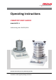
Operating instructions VIBRATORY SIEVE SHAKER ANALYSETTE 3 Valid starting with: 03.
Fritsch GmbH Milling and Sizing Industriestraße 8 D - 55743 Idar-Oberstein Telephone: +49 (0)6784/ 70-0 Fax: +49 (0)6784/ 70-11 email: info@fritsch.de Internet: www.fritsch.
Certifications and CE conformity Certifications and CE conformity Certification Fritsch GmbH has been certified by the TÜV-Zertifizierungsgemeinschaft e.V. An audit certified that Fritsch GmbH conforms to the requirements of the DIN EN ISO 9001:2008. CE Conformity The enclosed Conformity Declaration lists the guidelines the FRITSCH instrument conforms to, to be able to bear the CE mark.
Table of contents Table of contents 1 Basic structure............................................................................... 7 2 Safety information and use........................................................... 9 2.1 Requirements for the user..................................................... 9 2.2 Scope of application............................................................... 9 2.2.1 Operating principle........................................................... 10 2.2.
Table of contents 7 8 6.1.3 Feed quantity for dry or wet sieving................................. 6.2 Dry sieving............................................................................ 6.2.1 Sieving parameters........................................................... 6.2.2 Sieving aids........................................................................ 6.3 Wet sieving.......................................................................... 6.3.1 Sieving parameters..............................
Table of contents 9 Maintenance................................................................................ 44 9.1 Maintenance of the TorqueMaster clamping device........... 44 10 Repairs......................................................................................... 45 10.1 Checklist for troubleshooting............................................. 45 11 Disposal........................................................................................ 46 12 Guarantee terms................
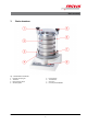
Basic structure 1 Basic structure Fig.
Basic structure Fig.
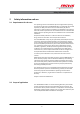
Safety information and use 2 Safety information and use 2.1 Requirements for the user This operating manual is intended for persons assigned with operating and monitoring the Fritsch the ANALYSETTE 3. The operating manual and especially its safety instructions are to be observed by all persons working on or with this device. In addition, the applicable rules and regulations for accident prevention at the installation site are to be observed.
Safety information and use CAUTION! The conversion of the "ANALYSETTE 3 PRO" to the micro mill "PULVERISETTE 0" cannot be recommended, as the amplitude control is unusable due to the ball collision malfunctions and therefore has no utility value. In this case, the "ANALYSETTE 3" SPARTAN is more suitable.
Safety information and use The amplitude of the ANALYSETTE 3 SPARTAN is set manually with the Plus and Minus key on the control panel and viewed on the lid. 2.3 Obligations of the operator Before using the the ANALYSETTE 3, this manual is to be carefully read and understood. The use of the the ANALYSETTE 3 requires technical knowledge; only commercial use is permitted. The operating personnel must be familiar with the content of the operating manual.
Safety information and use WARNING! This symbol and keyword combination points out a possibly hazardous situation that can result in death or serious injury if not avoided. CAUTION! This symbol and keyword combination points out a possibly hazardous situation that can result in slight or minor injury if not avoided. NOTICE! This symbol and keyword combination points out a possibly hazardous situation that can result in property damage if not avoided.
Safety information and use DANGER! This symbol and keyword combination designates contents and instructions for proper use of the machine with combustible substances. Ignoring information with this designation will result in serious or fatal injury. WARNING! This symbol and keyword combination points out a directly hazardous situation due to movable parts. Ignoring information with this designation can result in hand injuries.
Safety information and use Further designations To emphasise procedure instructions, results, lists, references and other elements, the following designations are used in this manual: Designation Explanation Step-by-step procedure instructions 1., 2., 3. ... ð Results of steps in the procedure References to sections in this manual and relevant documentation Lists without a specific order [Button] Operating elements (e.g. push button, switch), display elements (e.g.
Safety information and use DANGER! Explosion hazard! – When Sieving oxidizable substances, e.g. metals or coal, there is a risk of spontaneous combustion (dust explosion) if the share of fine particles exceeds a certain percentage. When Sieving these kinds of substances, special safety measures must be taken and the work must be supervised from a specialist. – The high-speed rotor mill is not explosion protected and is not designed to sieve explosive materials. n Do not remove the information signs.
Safety information and use 2.7 Hazardous points n Crushing hazard at the sieve tensioning system n Crushing hazard between vibratory plate and housing 2.8 Electrical safety 2.8.1 General information The main switch separates the device from the mains on two poles. 2.8.2 Protection against restart After switching off at the main switch and switching on again, the START key must be pressed for start-up. 2.8.3 Overload protection The mains fuse provides overload protection.
Technical data 3 Technical data 3.1 Dimensions Without sieve set: 350 x 200 x 400 mm (width x height x depth) 3.2 Weight Net: 21 kg Gross: approx. 27 kg 3.3 Operating noise Emissions value of workplace according to DIN EN ISO 3746:2005 is up to 76.6 dB (A) for sieving gravel. The value fluctuates, depending on frequency, grinding stock and use of sieving aids. When grinding with the PULVERISETTE 0, the operating noise is greatly reduced by using the sound absorption hood made of plexiglas (order no.
Technical data 3.7 Electrical fuses n Fuse under mains switch (on the back of the device) Replacement: 4 A M micro fuse, 5 x 20 mm 3.8 Load The maximum load of the ANALYSETTE 3 for the sieve set with sieving stock is up to 6 kg! 3.
Installation 4 Installation 4.1 Transport The device is delivered in a cardboard box. In the case of delivery with several accessories, the device is delivered in a transport crate. WARNING! Improper lifting can lead to personal injury or property damage. The machine must only be lifted with suitable equipment by qualified personnel. The guarantee excludes all claims for damage due to improper transport. 4.
Installation 4.4 Ambient conditions WARNING! Mains voltage! – The device may only be operated indoors. – The surrounding air may not carry any electrically conductive dust. – Maximum relative humidity 80% for temperatures up to 31°C, linearly decreasing down to 50% relative humidity at 40°C. n The room temperature has to stay between 5 - 40°C. n Altitudes up to 2000 m n Degree of pollution 2 according to IEC 664. 4.
Installation 4.5.1 Adjusting the mains voltage CAUTION! Only qualified personnel may change the voltage range on the device! CAUTION! The voltage range may only be adjusted after the mains has been disconnected. CAUTION! If the values 06 or 07 are set at a voltage of 230V~, it will result in a defect in the sieve shaker during operation. Failure to observe this will render void the guarantee, and releases us from liability for any resulting damage to the device. 1. Switch main switch to "0". 2.
Initial start-up 5 Initial start-up Perform initial start-up only after all work as described in Ä Chapter 4 ‘Installation’ on page 19 has been carried out. 5.1 Switching on n The device must be connected to the power supply if this has not been done already. n Switch on the device with the main switch on the back of the device. n The POWER lamp on the control panel lights up. n The displays show the default setting. 5.2 Function check n Clamp 2 test sieves (2) with clamping lid (1).
Using the device 6 Using the device 6.1 Sieving with the ANALYSETTE 3 6.1.1 Fitting and clamping the sieves On the vibratory plate, it is possible to fit up to ‐ 10 sieves with a height of 50 mm (or 2") or ‐ 16 sieves with a height of 25 mm (or 1") between the sieve pan (collecting vessel) and clamping lid. The combination of sieves and sieve pan is called a sieve set. Make sure not to clamp more than 6 kg on the ANALYSETTE 3 (sieve set + sieving stock). 1.
Using the device 9. Move the clamping lever upwards. Make sure that the teeth of the toothed belt interlock with the teeth of the belt clamping device! 10. Then attach the knurled knobs to the holders of the sieve cover! 11. By turning the knurled knobs to the right, tighten the sieve stack evenly until the toothed belts are tightly clamped! If the two toothed belts are not evenly clamped, it is possible that the sieving stock will not be distributed evenly across the sieve surface. 12.
Using the device 6.1.3 Feed quantity for dry or wet sieving (Sieves with 200 mm diameter) Maximum load: ‐ Sieving stock < 1 kg ‐ Sieves and sieving stock < 6 kg 6.2 Dry sieving For dry sieving, use the dry sieve pan (without outlet) and the dry clamping lid (plexiglas clamping lid without nozzles). 6.2.1 Sieving parameters Parameters Coarse sample Fine sample Sieving time 3...20 min 15....30 min Amplitude 2.5....3 mm 1.5....2.
Using the device In this case, the sieve shaker controller can no longer set the optimal working point; the sieve shaker vibrates with a lower amplitude and frequency. The amplitude set point must be reduced accordingly in this case. When the machine has warmed up, the set point can be increased accordingly. 6.2.2 Sieving aids To shorten the sieving time, sieving aids can be attached in each of the sieves that have mesh widths larger than 32 µm.
Using the device 6.3.1 Sieving parameters Parameters Average High percentage of fine ground material Sieving time 3...10 min approx. 15 min Amplitude 6.3.2 2...2.5 mm Wetting agents Wetting agents improve dispersion. n Add tensides in liquid form (washing-up liquid, Dusazin etc.) in small amounts only (dropwise), to prevent frothing. n Add inorganic or organic salts like tetrasodium diphosphate or sodium lauryl sulfate and poly salts in amounts of 0.1 - 0.5 %. 6.3.
Using the device Before adding wetting agent through the opening (O), please stop the sieve shaker with the Stop key. 6.3.4 Extracting the passing particles In order to extract the rinsed out fine particles, the outlet hose can be connected e.g. to a suction funnel with filter paper. Clear liquid flowing from the sieve pan indicates the end of the sieving process. 6.3.
Using the device 6.4 Micro-precision sieving with the ANALYSETTE 3 PRO 6.4.1 Sieving parameters Parameters 1 micro sieve Max. 4 micro sieves Sieving time 20...30 min 60 min Amplitude in "MICRO" 0.1...0.2 mm operating mode 6.4.2 0.5 mm Feed quantity Depending on particle size and sieve aperture size, it is possible to sieve a maximum of 200 mg (up to 1 g for coarse sieves of 50 - 100 µm). Determine the suitable feed quantity through experiment. NOTICE! The device must be in "MICRO" operating mode.
Using the device 1 2 3 4 5 Clamping lid with a nozzle Clamping ring with fast locking clamp Sieve pan (with funnel) Sieve spacer ring with 2 seals Micro-precision sieve n Turn the rubber pad on the vibratory plate until three caps can be seen; there are three threaded bore holes under the caps. n Take off the caps and screw the sieve pan (with funnel) (3) onto the centre of the vibratory plate using the clamping elements and knurled screws.
Using the device Do not switch off the device during this work. When the device is switched off, the sample material can stick or glue to the sieves. Transfer (rinse) the sieve residue into weighed bottles and dry it. Now the lower sieves can be sieved further. Continue dismantling as described above. NOTICE! The sieve stack must remain filled with liquid during the entire sieving process. The sieve foils must not run dry! That can cause irreparable damage to the sieves.
Using the device 6.7 Setting the amplitude Selecting the amplitude: n The vertical oscillation amplitude can be set in 0.1 mm steps using the + / - keys. Values between 0.1 and 3 mm can be set with the ANALYSETTE 3 PRO. If the MICRO key is pressed (MICRO lights up), an amplitude between 0.1 and 0.5 mm can be set. (ANALYSETTE 3 PRO only!) 6.7.1 Displaying the amplitude After ANALYSETTE 3 PRO is started, the display above the amplitude setting indicates the actual amplitude.
Using the device 6.9 Saving and invoking the settings It is possible to save the amplitude settings: sieving time/grinding duration, interval length and MICRO on/off. There are 9 memory locations provided for this. n Save settings: Press SAVE key n Invoke settings: Press PROGRAM key When the PROGRAM key is pressed, the 9 memory locations appear in turn and the settings are displayed. 6.10 Micro sieving After pressing the MICRO key, a control lamp in the key lights up and the amplitude is set to 0.1 mm.
Accessories 7 Accessories 7.1 AUTOSIEVE program Together with the AUTOSIEVE program package, the serial interface makes it possible to control all functions of the sieve shaker using a computer and to ensure the reproducibility of the sieving processes. The automatic evaluation of sieving results has also reduced the workload. With the help of the AUTOSIEVE program package and scales, sieving results can be displayed and saved in different forms after weighing the individual fractions. 7.
Accessories 7.4 TorqueMaster As an alternative to standard clamping devices, the TorqueMaster can be used for faster and more accurate clamping. 1 2 3 TorqueMaster clamping unit with toothed belt Clamping lid Hexagon socket bit (5.5) 4 5 Cordless screwdriver (with battery and charger) Unclamping aid NOTICE! The unclamping aid included is to be used exclusively for releasing a clamped sieve stack (in case of malfunction of the cordless screwdriver).
Accessories 3. Insert the sieve set and pour in the sieving stock. 4. Fit the TorqueMaster clamping lid. 5. Place the clamping unit on the clamping lid. The clamping unit must be fitted as centrally as possible. NOTICE! This symmetry is ensured by correctly adjusting and securing the toothed belt. 6. Lightly tighten the toothed belts on both sides and move the clamping lever upwards, as described in Ä Chapter 6.1.1 ‘Fitting and clamping the sieves’ on page 23 under point 9.
Accessories CAUTION! Follow the separate operating instructions of the cordless screwdriver manufacturer. These are included with the device. When clamping, make sure to lift the TorqueMaster slightly (illustration 1 + 2). If the toothed belt is not slightly tensioned, it will be crushed in the TorqueMaster (illustration 3 + 4). 7.4.3 Releasing the TorqueMaster The TorqueMaster clamping device is also released with the cordless screwdriver.
Accessories 7.4.4 TorqueMaster malfunctions For all functions, the two indicators of the clamping unit must be in the green area. If one or both indicators are in the red area, proceed according to the following table. Malfunction Possible causes Rectify fault Both indicators in outer red area Clamping unit open too much Open the clamping unit to a lesser degree, the toothed belt clamp is possibly too tight and must be loosened by one tooth at the belt clamping device on both sides.
Accessories 7.5.1 7.5.1.1 Conducting a grinding operation Fitting and clamping the mortar 1. Move the clamping lever on the belt clamping device downwards and insert the toothed belt through the holder from the inside to the outside. (See Ä Chapter 6.1.1 ‘Fitting and clamping the sieves’ on page 23). 2. Place the mortar and the ball on the vibratory plate. The mortar must be positioned in the round gap of the vibratory plate without being wedged. 3.
Accessories There is a risk of the grinding ball destroying the lid. The grinding stock can be added to the mortar bowl either dry or in suspension. CAUTION! Do not allow any liquids to flow into the device. To reduce the grinding noise, we recommend using a sound absorption hood (order no. 00.0130.17). 7.5.1.2 7.5.1.3 Parameters Grinding duration 10 ... 30 min (average) Amplitude 1 ... 2 mm (max.) Feed quantity Max.
Accessories 1 2 3 4 5 6 7 Upper part Lower part Grinding ball 50 mm Mortar Bent tube ventilation Funnel for liquid nitrogen Amplitude display The lower part (2) is placed on the vibratory plate and the mortar with ball (3) and grinding stock is placed into the plastic surround. Then the upper part (1) is placed on the lower part, so that the seal ring in the upper part is resting on the mortar edge and the bent ventilation tube (5) is facing backwards and the amplitude display (7) is facing forwards.
Cleaning 8 Cleaning DANGER! Mains voltage! – Before beginning with cleaning work, disconnect the mains plug and protect the device against being unintentionally switched back on! – Do not allow any liquids to flow into the device. – Indicate cleaning work with warning signs. – Put safety equipment back into operation after cleaning work.
Cleaning As far as possible, clean the sieves after every use. The sieves can be dried in a drying cabinet at a maximum of 95 °C (rinsing with alcohol reduces the drying time). NOTICE! The sieve and grinding covers of accessories with plexiglas insert may only be heated to max. 60 °C. NOTICE! The plexiglas lid must not be cleaned with alcohol or organic solvents.
Maintenance 9 Maintenance DANGER! Mains voltage – Before beginning with maintenance work, unplug the mains plug and protect the device against being unintentionally switched back on again! – Indicate maintenance work with warning signs. – Maintenance work may only be performed by specialised personnel. – Put safety equipment back into operation after maintenance or repair work. We recommend keeping a safety logbook Ä Chapter 14 ‘Safety logbook’ on page 51, where all work (maintenance, repairs......
Repairs 10 Repairs DANGER! Mains voltage! – Before beginning with repair work, unplug the mains plug and protect the device against being unintentionally switched back on. – Indicate repair work with warning signs. – Repair work may only be performed by specialised personnel. – Put safety equipment back into operation after maintenance work. 10.
Disposal 11 Disposal It is hereby confirmed that FRITSCH has implemented the directive 2002/95/EC of the European Parliament and Council from 27th January 2003 for the limitation of the use of certain dangerous substances in electrical and electronic devices.
Guarantee terms 12 Guarantee terms Guarantee period As manufacturer, FRITSCH GmbH provides – above and beyond any guarantee claims against the seller – a guaranty valid for the duration of two years from the date of issue of the guarantee certificate supplied with the device. Within this guarantee period, we shall remedy all deficiencies due to material or manufacturing defects free of charge. Rectification may take the form of either repair or replacement of the device, at our sole discretion.
Guarantee terms Costs not covered by the guarantee This guarantee excludes any costs for transport, packaging or travel that accrue in the event the product must be sent to us or in the event that one of our specialist technicians is required to come to your site. Any servicing done by persons not authorised by us and any use of parts that are not original FRITSCH accessories and spare parts will void the guarantee.
Exclusion of liability 13 Exclusion of liability Before using the product, be sure to have read and understood this operating manual. The use of the product requires technical knowledge; only commercial use is permitted. The product may be used exclusively within the scope of applications set down in this operating manual and within the framework of guidelines put forth in this operating manual and must be subject to regular maintenance.
Exclusion of liability Fritsch GmbH excludes any liability, warranty, or other obligation to compensate for damages, regardless of whether this liability, warranty, or other obligation is explicit or implicit, contractual or arising from unlawful acts or prescribed contractually, by law, or otherwise.
Safety logbook 14 Date Safety logbook Maintenance / Repair Name - 51 - Signature
Safety logbook Date Maintenance / Repair Name - 52 - Signature
Index 15 Index Installation . . . . . . . . . . . . . . . . . . . . . . . . . . . . . 19 Interval time . . . . . . . . . . . . . . . . . . . . . . . . . . . . 32 A Accident prevention . . . . . . . . . . . . . . . . . . . . . . . . 9 Adjusting to the mains voltage . . . . . . . . . . . . . . . 21 Ambient conditions . . . . . . . . . . . . . . . . . . . . . . . 20 Authorised persons . . . . . . . . . . . . . . . . . . . . . . . . 9 Autosieve . . . . . . . . . . . . . . . . . . . . . . . . . . . . . .
Index Weight . . . . . . . . . . . . . . . . . . . . . . . . . . . . . . . . 17 Wet sieving . . . . . . . . . . . . . . . . . . . . . . . . . . . . . 26 Wet sieving with micro-precision sieves . . . . . . . . . 30 W Warning information . . . . . . . . . . . . . . . . . . . . . . 11 WEEE . . . . . . . . . . . . . . . . . . . . . . . . . . . . . . . . .
© 2014 Fritsch GmbH Milling and Sizing Industriestraße 8 D - 55743 Idar-Oberstein Telephone: +49 (0)6784/ 70-0 Fax: +49 (0)6784/ 70-11 email: info@fritsch.de Internet: www.fritsch.