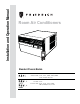
Installation and Operation Manual Room Air Conditioners AUTO FAN CONTINUOUS AUTO C F SYSTEM FAN MODE POWER FAN SPEED SCHEDULE Standard Chassis Models 115-Volt: S S 08 , S S10, S S12, S S14, SM15 208-230-Volt: S S12, S S15 , SM18 , SM21, SM24 SL 22, SL 24, SL 28, SL 36 115-Volt: Y S10 208-230-Volt: E S12, E S15 , Y S12 , E M18 Y M18, E M24, E L 36, Y L 24
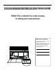
your unit to assure quiet operation, the greatest circulation of cool, dry air, and the most economic operation. THANK YOU, on behalf of our entire company, for making such a wise purchase. Register your air conditioner Model information can be found on the name plate behind the front cover. Please complete and mail the owner registration card furnished with this product, or register online at www.friedrich.com. For your future convenience, record the model information here.
Table of Contents Safety Precautions ................................................................................................................................................................................................................... 4 Unpacking Instructions.............................................................................................................................................................................................................
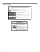
Safety Precautions Your safety and the safety of others are very important. We have provided many important safety messages in this manual and on your appliance. Always read and obey all safety messages. This is a safety Alert symbol. This symbol alerts you to potential hazards that can kill or hurt you and others. All safety messages will follow the safety alert symbol with the word “WARNING” or “CAUTION”.
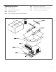
Unpacking Instructions STEP 5. Slide the foam front support forward STEP 1. Cut all 4 packing straps. STEP 6. Carefully lift decorative front box from foam front support STEP 2. Remove wooden shipping bar dividers. STEP 7. Remove decorative front and set safely aside STEP 3. Remove top foam pads. STEP 4. Slowly remove outer box, careful not to loosen decorative front.
WARNI NG: Before Operating Your Unit NOTICE WARNING Electrical Shock Hazard Make sure your electrical receptacle has the same configuration as your air conditioner’s plug. If different, consult a Licensed Electrician. Do not use plug adapters. Do not use an extension cord. Do not remove ground prong. Always plug into a grounded 3 prong oulet. Failure to follow these instructions can result in death, fire, or electrical shock. M ake sure the wiring is adequate for your unit.
Standard Filter Cleaning / Installation Instructions STEP 2. STEP 1. NOTE: Figure 2 Figure 4 FILTER FILTER GRIP FRR071 Figure 3 FRR047 STEP 3. Swing the front frame open. Clean the front frame by washing Figure 5 FILTER GRIP A TOP TAB HANDLE FRONT FRAME WITH STANDARD MESH FILTER FRR052 FRR048 STEP 4. NOTE: the tab in the frame stops the handle from sliding in, slide the handle from the other direction. Do not force the handle into the frame. STEP 5. the inside of the front door.
Premium Carbon Filter Installation Instructions STEP 4. STEP 1. STEP 2. NOTE: in Figure 4. STEP 3. STEP 5. and slide the assembly into the unit as per the instructions on the door. as shown in Figure 6. NOTE: Make sure the frame with the mesh is facing towards you. NOTE: the tab in the frame stops the handle from sliding in, slide the handle from the other direction. Do not force the handle into the frame.
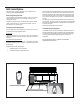
Control Panel Operation Let’s check out how to control your air conditioner. On the control panel, just above the POWER , is a liquid crystal display (LCD). All of the control panel function buttons and mode icons can be viewed in Figure 8. Power On – Press the button to turn on the air conditioner. The power button illuminates to indicate that the power is on. The backlight on the power switch will automatically dim to 20% intensity after 15 seconds of inactivity.
Kühl Control Options The Kühl gives you a variety of options for control, programming, and scheduling including wireless capabilities Wireless Programming and Control: . The new FriedrichLink™ Adapter (sold seperately) allows you to conviently control, program and monitor your air conditioning unit remotely from a smartphone or computer. FriedrichLink™ Adapter accessory available through Friedrich authorized retailers or www.friedrich.com. See FriedrichLink™ Adapter section on www.friedrich.
FAN ONLY MODE Control Panel Operation Instructions SYSTEM - The button allows you to sequentially select up to four modes of operation: AUTO - AUTO - Not available on some models SYSTEM COOL Not available on some models HEAT FAN ONLY AUTO MODE FRR105 - AUTO - When in the - AUTO-, COOL or HEAT or FAN ONLY mode, you can also select FAN MODE, FAN SPEED, TIMER SCHEDULE, and . The SYSTEM MODE does not change. F AUTO FAN FAN MODE – The CONTINUOUS modes.
CONTINUOUS The F CONTINUOUS SET POINT F AUTO FAN SET POINT FRR113 In the CONTINUOUS fan mode, the fan operates all the time. The system FRR123 UP and DOWN - arrows - Pressing either or button changes the system's set point (desired room temperature). These buttons are also used to make system parameter changes latter in this manual. The icon illuminates. system ON and OFF time window. For example, you can command the system to turn ON at 8:15 am and turn OFF at 1:30 pm everyday.
To switch from degrees Fahrenheit (F) to Celsius (C), press buttons for three seconds. or FRR129 Use the or buttons to adjust the minutes. The clock is now set for 11:25 AM. Press TIMER SET (Refer to Figure 10) button to display the unit's day setting. FRR133 from F to C, press the or button within 5 seconds. FRR134 FRR130 Use the or buttons to adjust the day (1 to 7). The day setting is up to the you the user. If you set the current day = 1, and today is Tuesday, then Day 1 = Tuesday.
F AUTO FAN SET POINT FRR193 The 2 indicates a DIM setting of 20%. Press the TIMER SET button within 15 seconds to save the setting. Button inactivity for more than 15 seconds causes the display to time out and return to the normal operating display. FRR120 This means there is a compressor demand but the system is not ready for the compressor to operate. For example a short power outage, the compressor will not restart until the internal pressures of the compressor are at the proper level.
External Control Status The $MART icon illuminates to indicate that the system is being controlled remotely. AUTO FAN 79 3. Commercial Schedule - When selected the unit follows a preprogrammed set of operational parameters that covers 7 days of the week with 2 time windows during each day. Each time window ! " # $ F 1 SET POINT $MART SCHEDULE FRR125 FRR137 AUTO FAN 79 To change the button for 3 sec.
AUTO FAN 79 F SET POINT FRR139 \ button is pressed the system operates in the mode (1, 2 or 3) you programmed. FRR143 The display returns to normal once the settings are saved.
AUTO FAN 79 F AUTO FAN SET POINT 79 SET POINT F SCHEDULE FRR147 The display returns to normal once the settings are saved. Timer - Scheduler Control Block AUTO FAN 79 SET POINT FRR151 The Timer ] { [ ] are made, press the button to re-activate Timer or Schedule mode.
AUTO FAN 79 SET POINT F AUTO FAN 79 F SET POINT SCHEDULE FRR159 FRR155 < * SCHEDULE and Timer icons illuminates. The control system immediately runs the previous (non-skip) period schedule parameters. < * illuminates. The control system continues to run.
AUTO FAN 79 F AUTO FAN SET POINT 79 F SET POINT FRR163 < [ ^ ` * the Timer and SCHEDULE icons turn off. The unit wakes up in the last known non-schedule state. AUTO FAN 79 SET POINT FRR167 < [ ^ ` * Timer icon turns off. The display shows a normal system.
FAN SPEED Button - Used to sequentially select new fan speed, plus FA N AUTO operation. When the SPEED button is pressed, the fan speed icon (triangle) changes to indicate the new speed level. Fan speed automatically varies depending on the set temperature on the control panel and the actual room temperature. For example if there is a big difference between your set temperature and the actual room temperature, the system fan speed increases to HIGH.
Figure 12 DISPLAY AUTO AUTO FAN CONTINUOUS AUTO C F SYSTEM FAN MODE SYSTEM FAN MODE POWER TEMPERATURE UP POWER FAN SPEED TEMPERATURE DOWN SCHEDULE SCHEDULE FAN SPEED FRR081 Figure 13 COOL ICON HEAT ICON FAN ONLY ICON SYSTEM MODE AUTO FAN MODE FAN SPEED AUTO FAN CONTINUOUS AUTO C F °F / °C ICONs SCHEDULE ICON FRR082 21
Airflow Selection and Adjustment Figure 14 Air flow direction adjustment left or right side of the discharge opening. Each of the banks of louvers can be directed left, right, up or down in order to achieve the most optimum move it in the direction that you would like the air to be directed. Please louvers than the other. Fresh air and exhaust control Your air conditioner has the ability to bring fresh air into the room or exhaust stale air out of the room.
Installation Instructions The following instructions are for standard chassis model groups READ THIS FIRST! Electrical Requirements sizes listed in Table 3. Table 3 MODEL DESIGNATION WARNING CABINET SIZE (H x W x D) SMALL CHASSIS - SS, 15 15 16" x 25 15 16" x 29" (405 mm x ES, YS 660 mm x 737 mm) Electrical Shock Hazard Make sure your electrical receptacle has the same configuration as your air conditioner’s plug. If different, consult a Licensed Electrician. Do not use plug adapters.
INSTALLATION HARDWARE AND ACCESSORY DETAIL ITEM 2 ITEM 3 ITEM 1 ITEM 5 ITEM 6 ITEM 4 ITEM 7 ITEM 8 ITEM 12 ITEM 11 ITEM 10 ITEM 9 ITEM 13 ITEMS NOT TO SCALE FRR009 ITEM NO DESCRIPTION QTY. 8 9 10 11 WINGBOARD MOUNTING PARTS WINGBOARD (MASONITE) "J" TYPE SPEED NUT WINGBOARD CLIP (SPRING STEEL) SCREW, #8 x ½" PHILLIPS TRUSS HD.
Standard Window Installation Figure 16 NOTE: Hardware and accessories used during installation are shown on page 23. Each part will be referred as Item No. STEP 1. Remove the chassis Entrygard retainer by removing the far right screw (See Figure 15), save this screw to reattach the chassis retainer after installation (Step 12). Also, remove and discard the two retainer screws and washers located at the rear of the unit (See Figure 15). CAUTION Use Handle Locations (both sides) STEP 2. STEP 3.
NOTE: CAUTION STEP 5. STEP 6. STEP 7. DO NOT LEVEL the cabinet from front to back. Make sure there is approximately 3/8” to 1/2” slope (1/8 to 1/4 bubble on level) toward the outside of the house. Remove Shipping Blocks Prior to operating the unit remove the foam shipping blocks. Adjust the support brackets to provide an inside-to-outside slope for excess condensation drainage (Refer to Standard Window Installation, Figures 20 through 24). Tighten all screws.
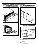
Figure 1 #8 x 3/8” LONG SCREW (ITEM 7) 2 REQUIRED CABINET TOP ANGLE (ITEM 5) TAB DETAIL B-2 SIDE ANGLE (ITEM 6) 2 REQUIRED TAB LOOP SILL PLATE TAB DETAIL B-1 FRR013 Figure 1 TOP ANGLE (ITEM 5) CENTER CABINET IN WINDOW SIDE TO SIDE PULL WINDOW SASH DOWN BEHIND TOP ANGLE DRILL (3) 5/32” DIA.
Figure 3/8” SLOPE DOWN #10-24 x 1” HEX HD. SCREW (ITEM 2) SUPPORT BRACKET (ITEM 1) #12 x 2” SCREW (ITEM 4) SUPPORT BRACKET (ITEM 1) SPACER SHOULD BE USED BETWEEN WALL AND BRACKET WHEN INSTALLED ON ALUMINUM OR VINYL SIDING. 10-24 x FLAT WELD NUT (ITEM 3) FRR015 Figure 2 3/8” SLOPE DOWN CONDENSER AIR OUTLET CONDENSER AIR INLETS #10-24 SCREW #10-24 FLAT WELD NUT #12 x 2” SHEET METAL SCREW (ITEM 4) SPACER SHOULD BE USED BETWEEN WALL AND BRACKET WHEN INSTALLED ON ALUMINUM OR VINYL SIDING.
Figure 2 3/8” SLOPE DOWN CONDENSER AIR INLETS #10-24 SCREW #10-24 FLAT WELD NUT STONE LEDGE #12 x 2” SHEET METAL SCREW (ITEM 4) SPACER FRR017 Figure 2 3/8” SLOPE DOWN #10-24 SCREW STRAIGHTEN TAB TO LAY FLAT ALONG THE BOTTOM RAIL OF THE SHELL #10-24 FLAT WELD NUT SECURE THE LONGEST SIDE OF THE BRACKET TO THE SHELL ADJUST IN OR OUT TO REST ON THE LEDGE STONE LEDGE FRR018
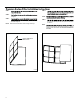
Figure 2 3/8” SLOPE DOWN #10-24 SCREW DIMENSION “A” CUT HERE CUT TO FIT DIMENSION “A” AND BEND DOWN TO FORM A VERTICAL LEG. #10-24 FLAT WELD NUT STONE LEDGE A OUTSIDE WALL DISCARD SHADED AREA FRR019 Figure 2 MEASURE DISTANCE “B” TO INSIDE OF THE CHANNEL ON EACH SIDE. CUT HERE AND DISCARD CENTER WASTE MATERIAL. B B WINGBOARD B B SUBTRACT 1/8” FROM DIMENSION “B” AND MEASURE FROM THE EDGE OF THE WINGBOARD (ITEM 8), MARK, SCORE AND CUT WITH APPROPRIATE CUTTING TOOL.
STEP 10. INSTALL THE WINDOW SEALING GASKETS – Measure and cut the dark foam window seal gasket (Item 12) and install it between the upper glass panel and the top part of the window sash (Figure 28). CAUTION Cut/Sever Although great care has been taken to minimize sharp edges in the construction of your unit, use gloves or other hand protection when handling unit Failure to do so can result in minor to moderate personal injury.
Figure 27 Figure 28 TOP OF CABINET INSERT FOAM WINDOW SEAL GASKET (ITEM 12) PLACE WINGBOARD PANEL IN WINDOW JAM TO COMPRESS THE SPRINGS INSIDE THE RUNNERS, AND SWING THE WINGBOARD PANELS INTO PLACE AS INDICATED BY THE DASHED LINES. WINDOW JAM CLIP (ITEM 10) SECTION A-A B A A SECURE THE SIDE WINGBOARD PANELS TO THE SIDE ANGLES WITH FOUR (4) #8 x 1/2” LONG SCREWS (ITEM 11), TWO ON EACH SIDE.
OPTIONAL: The factor y assembles the supply cord so that it exits the left side of the unit at the bottom. At the consumer’s discretion, the supply cord can be routed to exit the right side of the unit. To do this, route the supply cord to the right side. Pull the supply cord taunt through the loops (Refer to Cord Routing Change, Figure 31) and route the cord down. STEP 13. Use Tool Provided Please use the provided tool to attach the decorative front to the chassis.
Cord Routing Change STEP 16. Unplug unit. Carefully pull out electrical control panel 1", but not all the way. Figure 33 WARNING 1 INCH Electrical Shock Hazard Make sure your electrical receptacle has the same configuration as your air conditioner’s plug. If different, consult a Licensed Electrician. Do not use plug adapters. Do not use an extension cord. Do not remove ground prong. Always plug into a grounded 3 prong oulet.
STEP 19. Carefully push electrical control panel back into chassis. Figure 36 STEP 21. If running power cord to the right of the unit install the cord into the cord retainer clips along the bottom front of the unit. Figure 38 ELECTRICAL CONTROL PANEL CORD RETAINER CLIPS FRR059 STEP 20. Reinstall the 3 screws removed earlier to secure electrical control panel.
Through-the-Wall Installation The following instructions apply to wood, masonry, brick, concrete or cinder block wall construction. STEP 1. Follow steps 1, 2, 3, and 4 of the "STANDARD WINDOW INSTALLATION" instructions beginning on page 25. STEP 2. CABINET PREPARATION – Remove the sill plate from the cabinet by removing two (4) nuts and screws (Figure 39). Note that the chassis retainer is secured by a right side nut and screw (Detail A, Figure 39).
Figure 39 BEFORE CABINET AFTER CABINET SCREW (4 REQUIRED) NOTE: HOLES IN SILL PLATE MOVED TO BACK SIDE SILL PLATE NUT (4 REQUIRED) DETAIL A TURN SILL PLATE END TO END NUT (4 REQUIRED) DETAIL C DETAIL B SCREW (4 REQUIRED) BEND TABS DOWN NOTE: SCREW AND NUT ORIENTATION NOW REVERSED. FRR026 Figure 40 TOP VIEW A CONDITIONED ROOM SIDE AIR MAXIMUM WALL THICKNESS CONDENSER AIR INTAKE LOUVERS 2" MINIMUM BOTH SIDES TOP VIEW SHOWING BEVELED SIDES FOR AIR INTAKE.
Figure 42 Figure 41 CAULK ALL SIDES INSIDE AND OUTSIDE CAULK ALL SIDES INSIDE AND OUTSIDE CABINET CABINET SHIM TO FILL IN VOID AT THE TOP AND SIDES WITH WOOD AS REQUIRED. SHIM TO FILL IN VOID AT THE TOP AND SIDES WITH WOOD AS REQUIRED. ELECTRICAL RECEPTACLE (SEE FIG. 42 FOR LOCATION NOTE) ELECTRICAL RECEPTACLE (SEE FIG.
STEP 6. Slide the cabinet into the hole far enough to allow the guide-channel of the sill plate to contact the inside wall surface (Figure 21). NOTE: STEP 7. Drill three (3) 5/32” diameter pilot holes (use the sill-plate holes as a guide) into the frame and install three (3) #12 x 2" long screws (Item 4) (Figure 21). STEP 8. NOTE: Alternate fasteners are required when securing the sill plate or support brackets to material other than wood (cinder block, brick, masonry or concrete).
Final Inspection & Start-up Checklist Inspect and ensure that all components and accessories have been installed properly and that they have not been damaged during the installation progress. Check the condensate water drain(s) to ensure that they are adequate for the removal of condensate water, and that they meet the approval of the end user. Heat pumps operate differently If your unit is a "Y", or heat pump model, there are some things that you will want to be aware of.
Routine Maintenance monthly, and more frequently if conditions warrant. The unit must be turned To Remove, Wash and Replace Filter Service and Assistance Before calling for service, please check the “Troubleshooting Tips” section 42 43 avoid unnecessary service calls, and save you the cost of a service call if the problem is not due to the product itself. If you have checked the “Basic Troubleshooting” section and still need help, it is available as follows: our web site at www.friedrich.com.
Troubleshooting Tips @ >}Z < Unit does not operate. X @ @ X ? ZX < The unit is turned to the off position, Turn the unit to the on position and raise or lower temperature setting (as appropriate) to call for operation. Z@V< Plug into a properly grounded 3 prong receptacle. ? # ] proper receptacle type for your unit.
@ >}Z < X V @ J # * @ ^ ` @ X ? ZX < The outside temperature is below _ ^$ @` V cooling mode when the outside temperature is ] _ ^$ @` * and the unit may be damaged. The digital control is set to fan cycling mode. Since the fan does not circulate the room air continuously at this setting, the room air does not \
Addendum 1 Schedule Table with Energy Saving Values Residen al Schedule Period 600 Cool Auto Low 78 70 800 Cool Auto Low 85 62 Mon Start Time System Mode Fan Mode Fan Speed Set Point Cool Set Point Heat Start Time System Mode Fan Mode Fan Speed Set Point Cool Set Point Heat 3 Start Time System Mode Fan Mode Fan Speed Set Point Cool Set Point Heat 1800 Cool Auto Low 78 70 4 Start Time System Mode Fan Mode Fan Speed Set Point Cool Set Point Heat 1 2 Sun Start Time System Mode Fan Mode Fan Speed Set
Friedrich Air Conditioning Company 10001 Reunion Place, Suite 500 San Antonio, TX 78216 1-800-541-6645 www.friedrich.
Friedrich Air Conditioning Co. 10001 Reunion Place, Suite 50 San Antonio, Texas 78216 1-800-541-66450 www.friedrich.com Printed in the U.S.A.