
Service and Parts Manual (2018, 2019, 2020, 2021, 2022)

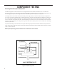


Table Of Contents
- INTRODUCTION
- Important Safety Information
- Personal Injury Or Death Hazards
- Operation of Equipment in During Construction
- Typical Unit Components and Dimensions
- Model Number Reference Guide
- Serial Number Reference Guide
- Product Features
- General Specifications 9-12k Heat Pump Models
- Electrical Data
- Function and Control
- Buttons and Display
- Temperature Definition
- System Basic Function
- 1) Cooling Mode
- 2) Heating Mode
- 3) Room Freeze Protection (AUTO HEATING)
- 4) Temperature Sensor Open Circuit or Short Circuit Protection
- 5) Power cut protection
- 6) Compressor and DC-inverter features
- 7) Smart fresh air system
- Advanced Functions
- Advanced Settings
- Memory Function
- FD Control (front-desk control) & 24V REMOTE THERMOSTAT
- Protection Functions
- System Configuration Fresh Air Vent Control
- Digital Control User Input Configuration
- Settings- Detailed Configurations
- Refrigeration Sequence Of Operation
- Refrigerant System Diagram
- PTAC Installation Recommendations
- Wall Sleeve Installation Instructions (PDXWS)
- Alternate Wall Installations
- PXDR10 Drain Kit Installation
- External Drain
- PXGA Standard Grille
- Chassis Install
- Remote Control Thermostat Installation
- Front Desk Control Terminal
- Final Inspection & Start-up Checklist
- Remove Chassis
- Remove User Interface
- Open Electrical Control Box
- Remove Main PCB (logic) Board
- Remove Power Cord
- Remove Power PCB
- Remove IPM PCB (Inverter Board)
- Remove Blower Wheel (Inside Fan)
- Remove Blower Wheel Motor (Inside Fan)
- Remove Heating Element
- Remove Freshaire Components
- Remove Outdoor Fan
- Remove Reversing valve Solenoid
- Refrigerant Charging
- Undercharged Refrigerant Systems
- Overcharged Refrigerant Systems
- Restricted Refrigerant System
- Sealed System Method of Charging/ Repairs
- Hermetic Components Check
- Reversing Valve Description And Operation
- Testing The Reversing Valve Solenoid Coil
- Checking The Reversing Valve
- Touch Test Chart : To Service Reversing Valves
- Compressor Checks
- Compressor Replacement
- Compressor Replacement -Special Procedure in Case of Compressor Burnout
- Check Indoor Fan Motor
- Check Outdoor Fan Motor
- Check Fan Motor Capacitors
- Main PCB (logic) Board Connector Identification
- Power PCB (Power Board) Connector Identification
- Basic Troubleshooting
- Error code and solutions
- Unit Does Not Operate
- Check Electric Heater Control
- Check Thermistors
- Check Thermistors -Resistance Table of Thermistors (5K)
- Check Thermistors -Resistance Table of Thermistors (50K)(Compressor Discharge Sensor)
- PARTS CATALOG

78 PB
WARNING
ELECTRIC SHOCK HAZARD
Turn off electric power before service or
installation. Extreme care must be used, if it
becomes necessary to work on equipment with
power applied.
Failure to do so could result in serious injury or
death.
WARNING
HIGH PRESSURE HAZARD
Sealed Refrigeration System contains refrigerant
and oil under high pressure.
Proper safety procedures must be followed,
and proper protective clothing must be worn
when working with refrigerants.
Failure to follow these procedures could
result in serious injury or death.
Figure 705 (Compressor Windings)
COMPONENT TESTING
Compressor Checks
DC
INVERTER
&
R U( )
S V( )
CONTROLLER
T W( )
POWER
OVERLOAD PROT ECTION
Gain access to compressor and IPM PCB (Inverter
Board) by removing chassis from wall. Refer to
Figure 5xx
1) Disconnect terminals R(U), S(V), and T(W) from
the compressor.
Resistance Test.
2) Set Ohm meter to the lowest scale and check
continuity between pins R(U), S(V), and T(W).
At room temperature (70°- 95°F) the resistance
should be approximately 2.2 ohms. The Ohm values
will change signicantly at different temperatures.
This does not indicate that the compressor wind-
ings are faulty. A reading of open (innity), or a
signicant difference in the resistance between the
windings does indicate that the compressor wind-
ings are faulty.
3) Check for continuity from between pins R(U) to
ground, S(V) to ground, and T(U) to ground)
The compressor windings are faulty if the there is
continuity from the compressor windings to ground.
4)Common signs compressor is faulty:
• Compressor motor lock.
• Discharge pressure value approaches static
pressure value .
• Compressor motor winding abnormality.
Note:
• Don’t put a compressor on its side or turn over.
• Assemble the compressor quickly after remov-
ing the plugs. Prolonged exposure will damage
the internal components of the compressor
• Ensure wiring is correct before operating.
Reverse operation will permanently damage
the compressor.
• Electric Reactor
Common Problems:
• Sound abnormality
• Runs in a sporadic rhythm.