
Service and Parts Manual (2018, 2019, 2020, 2021, 2022)

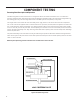


Table Of Contents
- INTRODUCTION
- Important Safety Information
- Personal Injury Or Death Hazards
- Operation of Equipment in During Construction
- Typical Unit Components and Dimensions
- Model Number Reference Guide
- Serial Number Reference Guide
- Product Features
- General Specifications 9-12k Heat Pump Models
- Electrical Data
- Function and Control
- Buttons and Display
- Temperature Definition
- System Basic Function
- 1) Cooling Mode
- 2) Heating Mode
- 3) Room Freeze Protection (AUTO HEATING)
- 4) Temperature Sensor Open Circuit or Short Circuit Protection
- 5) Power cut protection
- 6) Compressor and DC-inverter features
- 7) Smart fresh air system
- Advanced Functions
- Advanced Settings
- Memory Function
- FD Control (front-desk control) & 24V REMOTE THERMOSTAT
- Protection Functions
- System Configuration Fresh Air Vent Control
- Digital Control User Input Configuration
- Settings- Detailed Configurations
- Refrigeration Sequence Of Operation
- Refrigerant System Diagram
- PTAC Installation Recommendations
- Wall Sleeve Installation Instructions (PDXWS)
- Alternate Wall Installations
- PXDR10 Drain Kit Installation
- External Drain
- PXGA Standard Grille
- Chassis Install
- Remote Control Thermostat Installation
- Front Desk Control Terminal
- Final Inspection & Start-up Checklist
- Remove Chassis
- Remove User Interface
- Open Electrical Control Box
- Remove Main PCB (logic) Board
- Remove Power Cord
- Remove Power PCB
- Remove IPM PCB (Inverter Board)
- Remove Blower Wheel (Inside Fan)
- Remove Blower Wheel Motor (Inside Fan)
- Remove Heating Element
- Remove Freshaire Components
- Remove Outdoor Fan
- Remove Reversing valve Solenoid
- Refrigerant Charging
- Undercharged Refrigerant Systems
- Overcharged Refrigerant Systems
- Restricted Refrigerant System
- Sealed System Method of Charging/ Repairs
- Hermetic Components Check
- Reversing Valve Description And Operation
- Testing The Reversing Valve Solenoid Coil
- Checking The Reversing Valve
- Touch Test Chart : To Service Reversing Valves
- Compressor Checks
- Compressor Replacement
- Compressor Replacement -Special Procedure in Case of Compressor Burnout
- Check Indoor Fan Motor
- Check Outdoor Fan Motor
- Check Fan Motor Capacitors
- Main PCB (logic) Board Connector Identification
- Power PCB (Power Board) Connector Identification
- Basic Troubleshooting
- Error code and solutions
- Unit Does Not Operate
- Check Electric Heater Control
- Check Thermistors
- Check Thermistors -Resistance Table of Thermistors (5K)
- Check Thermistors -Resistance Table of Thermistors (50K)(Compressor Discharge Sensor)
- PARTS CATALOG

77 PB
COMPONENT TESTING
Compressor Checks
Overloads
The compressor is equipped with either an external or internal overload which senses both motor amperage and winding
temperature. High motor temperature or amperage heats the overload causing it to open, breaking the common circuit within
the compressor. Heat generated within the compressor shell, usually due to recycling of the motor, is slow to dissipate. It may
take anywhere from a few minutes to several hours for the overload to reset.
Checking the Overloads
External Overloads
With power off, remove the leads from compressor terminals. If the compressor is hot, allow the overload to cool before
starting check. Using an ohmmeter, test continuity across the terminals of the external overload. If you do not have continuity;
this indicates that the overload is open and must be replaced.
Internal Overloads
The overload is embedded in the motor windings to sense the winding temperature and/or current draw. The overload is
connected in series with the common motor terminal.
Should the internal temperature and/or current draw become excessive, the contacts in the overload will open, turning off the
compressor. The overload will automatically reset, but may require several hours before the heat is dissipated.
Checking the Internal Overload
1. With no power to unit, remove the leads from the compressor terminals.
2. Using an ohmmeter, test continuity between terminals C-S and C-R. If no continuity, the compressor overload is open and
the compressor must be replaced.
WARNING
ELECTRIC SHOCK HAZARD
Turn off electric power before service or
installation.
All electrical connections and wiring MUST be
the National Electrical Code and all local codes
which have jurisdiction.
Failure to do so can result in personal injury or
death.
BURN HAZARD
Proper safety procedures must be followed,
and proper protective clothing must be worn
when working with a torch.
Failure to follow these procedures could
result in moderate or serious injury.
WARNING