
Service and Parts Manual (2018, 2019, 2020, 2021, 2022)

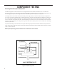


Table Of Contents
- INTRODUCTION
- Important Safety Information
- Personal Injury Or Death Hazards
- Operation of Equipment in During Construction
- Typical Unit Components and Dimensions
- Model Number Reference Guide
- Serial Number Reference Guide
- Product Features
- General Specifications 9-12k Heat Pump Models
- Electrical Data
- Function and Control
- Buttons and Display
- Temperature Definition
- System Basic Function
- 1) Cooling Mode
- 2) Heating Mode
- 3) Room Freeze Protection (AUTO HEATING)
- 4) Temperature Sensor Open Circuit or Short Circuit Protection
- 5) Power cut protection
- 6) Compressor and DC-inverter features
- 7) Smart fresh air system
- Advanced Functions
- Advanced Settings
- Memory Function
- FD Control (front-desk control) & 24V REMOTE THERMOSTAT
- Protection Functions
- System Configuration Fresh Air Vent Control
- Digital Control User Input Configuration
- Settings- Detailed Configurations
- Refrigeration Sequence Of Operation
- Refrigerant System Diagram
- PTAC Installation Recommendations
- Wall Sleeve Installation Instructions (PDXWS)
- Alternate Wall Installations
- PXDR10 Drain Kit Installation
- External Drain
- PXGA Standard Grille
- Chassis Install
- Remote Control Thermostat Installation
- Front Desk Control Terminal
- Final Inspection & Start-up Checklist
- Remove Chassis
- Remove User Interface
- Open Electrical Control Box
- Remove Main PCB (logic) Board
- Remove Power Cord
- Remove Power PCB
- Remove IPM PCB (Inverter Board)
- Remove Blower Wheel (Inside Fan)
- Remove Blower Wheel Motor (Inside Fan)
- Remove Heating Element
- Remove Freshaire Components
- Remove Outdoor Fan
- Remove Reversing valve Solenoid
- Refrigerant Charging
- Undercharged Refrigerant Systems
- Overcharged Refrigerant Systems
- Restricted Refrigerant System
- Sealed System Method of Charging/ Repairs
- Hermetic Components Check
- Reversing Valve Description And Operation
- Testing The Reversing Valve Solenoid Coil
- Checking The Reversing Valve
- Touch Test Chart : To Service Reversing Valves
- Compressor Checks
- Compressor Replacement
- Compressor Replacement -Special Procedure in Case of Compressor Burnout
- Check Indoor Fan Motor
- Check Outdoor Fan Motor
- Check Fan Motor Capacitors
- Main PCB (logic) Board Connector Identification
- Power PCB (Power Board) Connector Identification
- Basic Troubleshooting
- Error code and solutions
- Unit Does Not Operate
- Check Electric Heater Control
- Check Thermistors
- Check Thermistors -Resistance Table of Thermistors (5K)
- Check Thermistors -Resistance Table of Thermistors (50K)(Compressor Discharge Sensor)
- PARTS CATALOG

72 PB
COMPONENT TESTING
Reversing Valve Description And Operation
The Reversing Valve controls the direction of refrigerant ow to the indoor and outdoor coils. It consists of a
pressure-operated, main valve and a pilot valve actuated by a solenoid plunger. The solenoid is energized during
the heating cycle only. The reversing valves used in the RAC system is a 2-position, 4-way valve.
The single tube on one side of the main valve body is the high-pressure inlet to the valve from the compressor.
The center tube on the opposite side is connected to the low pressure (suction) side of the system. The other two
are connected to the indoor and outdoor coils. Small capillary tubes connect each end of the main valve cylinder
to the “A” and “B” ports of the pilot valve. A third capillary is a common return line from these ports to the suction
tube on the main valve body. Four-way reversing valves also have a capillary tube from the compressor discharge
tube to the pilot valve.
The piston assembly in the main valve can only be shifted by the pressure differential between the high and low
sides of the system. The pilot section of the valve opens and closes ports for the small capillary tubes to the main
valve to cause it to shift.
NOTE: System operating pressures must be near normal before valve can shift.
A
B
Figure 702 (Reversing Valve)