
Service and Parts Manual (2018, 2019, 2020, 2021, 2022)


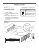
Table Of Contents
- INTRODUCTION
- Important Safety Information
- Personal Injury Or Death Hazards
- Operation of Equipment in During Construction
- Typical Unit Components and Dimensions
- Model Number Reference Guide
- Serial Number Reference Guide
- Product Features
- General Specifications 9-12k Heat Pump Models
- Electrical Data
- Function and Control
- Buttons and Display
- Temperature Definition
- System Basic Function
- 1) Cooling Mode
- 2) Heating Mode
- 3) Room Freeze Protection (AUTO HEATING)
- 4) Temperature Sensor Open Circuit or Short Circuit Protection
- 5) Power cut protection
- 6) Compressor and DC-inverter features
- 7) Smart fresh air system
- Advanced Functions
- Advanced Settings
- Memory Function
- FD Control (front-desk control) & 24V REMOTE THERMOSTAT
- Protection Functions
- System Configuration Fresh Air Vent Control
- Digital Control User Input Configuration
- Settings- Detailed Configurations
- Refrigeration Sequence Of Operation
- Refrigerant System Diagram
- PTAC Installation Recommendations
- Wall Sleeve Installation Instructions (PDXWS)
- Alternate Wall Installations
- PXDR10 Drain Kit Installation
- External Drain
- PXGA Standard Grille
- Chassis Install
- Remote Control Thermostat Installation
- Front Desk Control Terminal
- Final Inspection & Start-up Checklist
- Remove Chassis
- Remove User Interface
- Open Electrical Control Box
- Remove Main PCB (logic) Board
- Remove Power Cord
- Remove Power PCB
- Remove IPM PCB (Inverter Board)
- Remove Blower Wheel (Inside Fan)
- Remove Blower Wheel Motor (Inside Fan)
- Remove Heating Element
- Remove Freshaire Components
- Remove Outdoor Fan
- Remove Reversing valve Solenoid
- Refrigerant Charging
- Undercharged Refrigerant Systems
- Overcharged Refrigerant Systems
- Restricted Refrigerant System
- Sealed System Method of Charging/ Repairs
- Hermetic Components Check
- Reversing Valve Description And Operation
- Testing The Reversing Valve Solenoid Coil
- Checking The Reversing Valve
- Touch Test Chart : To Service Reversing Valves
- Compressor Checks
- Compressor Replacement
- Compressor Replacement -Special Procedure in Case of Compressor Burnout
- Check Indoor Fan Motor
- Check Outdoor Fan Motor
- Check Fan Motor Capacitors
- Main PCB (logic) Board Connector Identification
- Power PCB (Power Board) Connector Identification
- Basic Troubleshooting
- Error code and solutions
- Unit Does Not Operate
- Check Electric Heater Control
- Check Thermistors
- Check Thermistors -Resistance Table of Thermistors (5K)
- Check Thermistors -Resistance Table of Thermistors (50K)(Compressor Discharge Sensor)
- PARTS CATALOG

36 PB
INSTALLATION
Alternate Wall Installations
8
13-¾
"
Figure 8
Wall Sleeve Attachment
WALL
SLEEVE
ALTERNATE
FASTENING METHODS
(Field Supplied)
WOOD SCREW
TOGGLE BOLT
NOTE: The Wall Sleeve must be
horizontally level (side-to-side)
and pitched 1/4 bubble to the
outside when installed in an
opening.
The mounting hole location
EXPANSION
ANCHOR BOLT
should be approximately 2-4”
from the top and bottom of the
sleeve.
MOUNTING
HOLES
PLASTIC ANCHORS
SCREWS
FRP008
Figure 9
Dimensions
A ¼" MIN.
A B C
Dimension*
Allow
for wall
finishing
Allow
for floor
finishing
Allow
for proper
drainage
(Minimum) Min. Max.
(Front-to-Back)
C
No Accessories
¼" ¼"
---
---
With Subbase 1-¾" 3-½" 5"
---
With Lateral Duct
¾"
¼"
---
---
Wall Sleeve Tilt
B
--- --- ---
¼"
WALL
* If more than one accessory is to be used, use the maximum
dimension. If the wall thickness is more than 13-¾" - (A+ ¼"),
a sleeve extension must be used.
FRP009