
Service and Parts Manual (2018, 2019, 2020, 2021, 2022)


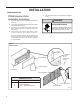
Table Of Contents
- INTRODUCTION
- Important Safety Information
- Personal Injury Or Death Hazards
- Operation of Equipment in During Construction
- Typical Unit Components and Dimensions
- Model Number Reference Guide
- Serial Number Reference Guide
- Product Features
- General Specifications 9-12k Heat Pump Models
- Electrical Data
- Function and Control
- Buttons and Display
- Temperature Definition
- System Basic Function
- 1) Cooling Mode
- 2) Heating Mode
- 3) Room Freeze Protection (AUTO HEATING)
- 4) Temperature Sensor Open Circuit or Short Circuit Protection
- 5) Power cut protection
- 6) Compressor and DC-inverter features
- 7) Smart fresh air system
- Advanced Functions
- Advanced Settings
- Memory Function
- FD Control (front-desk control) & 24V REMOTE THERMOSTAT
- Protection Functions
- System Configuration Fresh Air Vent Control
- Digital Control User Input Configuration
- Settings- Detailed Configurations
- Refrigeration Sequence Of Operation
- Refrigerant System Diagram
- PTAC Installation Recommendations
- Wall Sleeve Installation Instructions (PDXWS)
- Alternate Wall Installations
- PXDR10 Drain Kit Installation
- External Drain
- PXGA Standard Grille
- Chassis Install
- Remote Control Thermostat Installation
- Front Desk Control Terminal
- Final Inspection & Start-up Checklist
- Remove Chassis
- Remove User Interface
- Open Electrical Control Box
- Remove Main PCB (logic) Board
- Remove Power Cord
- Remove Power PCB
- Remove IPM PCB (Inverter Board)
- Remove Blower Wheel (Inside Fan)
- Remove Blower Wheel Motor (Inside Fan)
- Remove Heating Element
- Remove Freshaire Components
- Remove Outdoor Fan
- Remove Reversing valve Solenoid
- Refrigerant Charging
- Undercharged Refrigerant Systems
- Overcharged Refrigerant Systems
- Restricted Refrigerant System
- Sealed System Method of Charging/ Repairs
- Hermetic Components Check
- Reversing Valve Description And Operation
- Testing The Reversing Valve Solenoid Coil
- Checking The Reversing Valve
- Touch Test Chart : To Service Reversing Valves
- Compressor Checks
- Compressor Replacement
- Compressor Replacement -Special Procedure in Case of Compressor Burnout
- Check Indoor Fan Motor
- Check Outdoor Fan Motor
- Check Fan Motor Capacitors
- Main PCB (logic) Board Connector Identification
- Power PCB (Power Board) Connector Identification
- Basic Troubleshooting
- Error code and solutions
- Unit Does Not Operate
- Check Electric Heater Control
- Check Thermistors
- Check Thermistors -Resistance Table of Thermistors (5K)
- Check Thermistors -Resistance Table of Thermistors (50K)(Compressor Discharge Sensor)
- PARTS CATALOG

35 PB
INSTALLATION
Alternate Wall Installations
7
Figure 4
Panel Wall
Figure 6
Curtain Wall
WALL OR
WINDOW
1/4" MIN
PROJECTIO
N
CASE FLANGE
(BY OTHERS)
OPTIONAL SUBBASE
LEVELING SCREW
OPTIONAL SUBBASE
FRP004
LEVELING SCREW
FRP006
Figure 5
Frame and Brick Veneer
Figure 7
Block and Brick Veneer
1/4" MIN
PROJECTION
1/4" MIN
PROJECTION
WOOD FRAME
CONCRETE LINTEL
STEEL
LINTEL
13-3/4" MIN.
STEEL
LINTEL
11" MIN.
WITH SUBBASE
WITHOUT SUBBASE
OPTIONAL SUBBASE
LEVELING SCREW
FRP005
RECEPTACLE
FINISHED FLOOR
POWER SUPPLY CONDUIT
(SUPPLIED BY INSTALLER)
FRP007
NOTE: Follow all wall system manufacturer installation instructions. For sunrooms and modular buildings, adhere to their installation instructions for
supporting and sealing sleeve to their frames. All wall and window/wall installations must provide for proper drainage. In applications where the
drain holes on the PTAC wall sleeve are not exposed beyond the wall an internal drain system is recommended. It is the installer's responsibility
to ensure there is adequate drainage for the PTAC unit.