
Service and Parts Manual (2018, 2019, 2020, 2021, 2022)


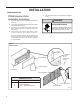
Table Of Contents
- INTRODUCTION
- Important Safety Information
- Personal Injury Or Death Hazards
- Operation of Equipment in During Construction
- Typical Unit Components and Dimensions
- Model Number Reference Guide
- Serial Number Reference Guide
- Product Features
- General Specifications 9-12k Heat Pump Models
- Electrical Data
- Function and Control
- Buttons and Display
- Temperature Definition
- System Basic Function
- 1) Cooling Mode
- 2) Heating Mode
- 3) Room Freeze Protection (AUTO HEATING)
- 4) Temperature Sensor Open Circuit or Short Circuit Protection
- 5) Power cut protection
- 6) Compressor and DC-inverter features
- 7) Smart fresh air system
- Advanced Functions
- Advanced Settings
- Memory Function
- FD Control (front-desk control) & 24V REMOTE THERMOSTAT
- Protection Functions
- System Configuration Fresh Air Vent Control
- Digital Control User Input Configuration
- Settings- Detailed Configurations
- Refrigeration Sequence Of Operation
- Refrigerant System Diagram
- PTAC Installation Recommendations
- Wall Sleeve Installation Instructions (PDXWS)
- Alternate Wall Installations
- PXDR10 Drain Kit Installation
- External Drain
- PXGA Standard Grille
- Chassis Install
- Remote Control Thermostat Installation
- Front Desk Control Terminal
- Final Inspection & Start-up Checklist
- Remove Chassis
- Remove User Interface
- Open Electrical Control Box
- Remove Main PCB (logic) Board
- Remove Power Cord
- Remove Power PCB
- Remove IPM PCB (Inverter Board)
- Remove Blower Wheel (Inside Fan)
- Remove Blower Wheel Motor (Inside Fan)
- Remove Heating Element
- Remove Freshaire Components
- Remove Outdoor Fan
- Remove Reversing valve Solenoid
- Refrigerant Charging
- Undercharged Refrigerant Systems
- Overcharged Refrigerant Systems
- Restricted Refrigerant System
- Sealed System Method of Charging/ Repairs
- Hermetic Components Check
- Reversing Valve Description And Operation
- Testing The Reversing Valve Solenoid Coil
- Checking The Reversing Valve
- Touch Test Chart : To Service Reversing Valves
- Compressor Checks
- Compressor Replacement
- Compressor Replacement -Special Procedure in Case of Compressor Burnout
- Check Indoor Fan Motor
- Check Outdoor Fan Motor
- Check Fan Motor Capacitors
- Main PCB (logic) Board Connector Identification
- Power PCB (Power Board) Connector Identification
- Basic Troubleshooting
- Error code and solutions
- Unit Does Not Operate
- Check Electric Heater Control
- Check Thermistors
- Check Thermistors -Resistance Table of Thermistors (5K)
- Check Thermistors -Resistance Table of Thermistors (50K)(Compressor Discharge Sensor)
- PARTS CATALOG

34 PB
INSTALLATION
Wall Sleeve Installation Instructions (PDXWS)
6
Wall Sleeve Installation Instructions (PDXWSA)
NOTE: Insure that the unit is only installed in a wall structurally adequate to support the unit including the sleeve, chassis and accessories.If the sleeve
projects more than 8" into the room, a subbase or other means of support MUST be used. Please read these instructions completely
before attempting installation.
WARNING
Falling Object Hazard
Not following Installation Instructions for
mounting your air conditioner can result
in property damage, injury, or death.
NOTICE
DO NOT allow any pitch toward the inside.
Flashing on all 4 sides of the opening is recommended.
Potential property damage can occur if instructions are
not followed.
For Deep Wall Installation (Greater than 13 1/4")
SeePage9
The following instructions apply ONLY to walls less than 13 ¼" in depth.
1 The PXDR10 Drain Kit,(optional for new construction) see page 10
if applicable, must be installed before the wall sleeve is installed
into the wall.
2 The External Drain (for new construction or unit replacement) see
page 11 if applicable, must be installed before the wall sleeve is
installed into the wall.
Figure 3
Typical Wall Sleeve Installation
3 From inside the building, position the wall sleeve in the opening and
push it into the wall until it protrudes at least ¼” on the outside
(See Figure 9, Page 8).
4 Position the wall sleeve with a slight tilt towards the outside to
facilitate condensate drainage. It should be level side-to-side and
the front should be ¼ bubble higher than the back.
ELECTRICAL
RECEPTACLE
LINTEL TO SUPPORT
MASONRY WALLS
42-¼"
MIN.
16-¼
"
60
"
MAX.
20
"
MAX.
13-¾"
SMOOTH SIDE OF SCREW
CLIP FACING INTO ROOM
ELECTRICAL
RECEPTACLE
INSULATION
WALL OPENING
WALL SLEEVE
INSULATION
NOTE:
All 230/208V units are manufactured with a 60” power cord and all 265V units with a 18” power cord.
FRP003