
Service and Parts Manual (2018, 2019, 2020, 2021, 2022)


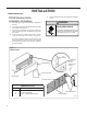
Table Of Contents
- INTRODUCTION
- Important Safety Information
- Personal Injury Or Death Hazards
- Operation of Equipment in During Construction
- Typical Unit Components and Dimensions
- Model Number Reference Guide
- Serial Number Reference Guide
- Product Features
- General Specifications 9-12k Heat Pump Models
- Electrical Data
- Function and Control
- Buttons and Display
- Temperature Definition
- System Basic Function
- 1) Cooling Mode
- 2) Heating Mode
- 3) Room Freeze Protection (AUTO HEATING)
- 4) Temperature Sensor Open Circuit or Short Circuit Protection
- 5) Power cut protection
- 6) Compressor and DC-inverter features
- 7) Smart fresh air system
- Advanced Functions
- Advanced Settings
- Memory Function
- FD Control (front-desk control) & 24V REMOTE THERMOSTAT
- Protection Functions
- System Configuration Fresh Air Vent Control
- Digital Control User Input Configuration
- Settings- Detailed Configurations
- Refrigeration Sequence Of Operation
- Refrigerant System Diagram
- PTAC Installation Recommendations
- Wall Sleeve Installation Instructions (PDXWS)
- Alternate Wall Installations
- PXDR10 Drain Kit Installation
- External Drain
- PXGA Standard Grille
- Chassis Install
- Remote Control Thermostat Installation
- Front Desk Control Terminal
- Final Inspection & Start-up Checklist
- Remove Chassis
- Remove User Interface
- Open Electrical Control Box
- Remove Main PCB (logic) Board
- Remove Power Cord
- Remove Power PCB
- Remove IPM PCB (Inverter Board)
- Remove Blower Wheel (Inside Fan)
- Remove Blower Wheel Motor (Inside Fan)
- Remove Heating Element
- Remove Freshaire Components
- Remove Outdoor Fan
- Remove Reversing valve Solenoid
- Refrigerant Charging
- Undercharged Refrigerant Systems
- Overcharged Refrigerant Systems
- Restricted Refrigerant System
- Sealed System Method of Charging/ Repairs
- Hermetic Components Check
- Reversing Valve Description And Operation
- Testing The Reversing Valve Solenoid Coil
- Checking The Reversing Valve
- Touch Test Chart : To Service Reversing Valves
- Compressor Checks
- Compressor Replacement
- Compressor Replacement -Special Procedure in Case of Compressor Burnout
- Check Indoor Fan Motor
- Check Outdoor Fan Motor
- Check Fan Motor Capacitors
- Main PCB (logic) Board Connector Identification
- Power PCB (Power Board) Connector Identification
- Basic Troubleshooting
- Error code and solutions
- Unit Does Not Operate
- Check Electric Heater Control
- Check Thermistors
- Check Thermistors -Resistance Table of Thermistors (5K)
- Check Thermistors -Resistance Table of Thermistors (50K)(Compressor Discharge Sensor)
- PARTS CATALOG

33 PB
INSTALLATION
PTAC Installation Recommendations
5
PTAC Installation Recommendations
For proper PTAC unit performance and maximum operating life refer to the minimum installation clearances
below:
Figure 1
PTAC units should be installed no
closer than 12" apart when two
units are side by side. If three or
more PTAC units are to operate
next to one another allow a
minimum of 36" between units.
Also,a vertical clearance of 60"
should be maintained between
units installed. In the interior of
the room the unit should be
located a minimum of 1/4" from the
floor and a minimum of 36"
from the ceiling.
FRP001
For PTACs on the ground floor or anytime obstructions are present, use the following guidelines:
Figure 2
• For minor obstructions
such as lamp poles or small
shrubbery a clearance of
12" from the outdoor louver
should be maintained.
TYPICAL BUILDING ( PLAN VIEW )
• For major obstructions such
as a solid fence, wall or
other heat rejecting device
like a condensing unit, a
minimum distance of 36"
should be kept.
PTAC
12" MINIMUM, MINOR
OBSTRUCTIONS
36" MIMUMUM, MAJOR
36"
POLE
PTAC
12"
36"
36"
SHRUB
PTAC
OBSTRUCTIONS
CONDENSING UNIT
FENCE OR WALL
FRP002
The above suggestions are for reference only and do not represent all possible installations.Please contact Friedrich for information regarding affects of other
installation arrangements.By following these simple recommendations you can be confident that your Friedrich PTAC will provide years of worry free operation.
THREE OR MORE PTACs
ADJACENT 36" MINIMUM
GROUND FLOOR PTACs
6" MINIMUM FROM GRADE
TWO ADJACENT PTACs
12" MINIMUM
TYPICAL
WINDOW
12"
6"
VIEW: OUTSIDE BUILDING ELEVATION
60" VERTICAL
MINIMUM
BETWEEN
PTACs
36"
60"