
Service and Parts Manual (2018, 2019, 2020, 2021, 2022)

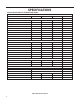


Table Of Contents
- INTRODUCTION
- Important Safety Information
- Personal Injury Or Death Hazards
- Operation of Equipment in During Construction
- Typical Unit Components and Dimensions
- Model Number Reference Guide
- Serial Number Reference Guide
- Product Features
- General Specifications 9-12k Heat Pump Models
- Electrical Data
- Function and Control
- Buttons and Display
- Temperature Definition
- System Basic Function
- 1) Cooling Mode
- 2) Heating Mode
- 3) Room Freeze Protection (AUTO HEATING)
- 4) Temperature Sensor Open Circuit or Short Circuit Protection
- 5) Power cut protection
- 6) Compressor and DC-inverter features
- 7) Smart fresh air system
- Advanced Functions
- Advanced Settings
- Memory Function
- FD Control (front-desk control) & 24V REMOTE THERMOSTAT
- Protection Functions
- System Configuration Fresh Air Vent Control
- Digital Control User Input Configuration
- Settings- Detailed Configurations
- Refrigeration Sequence Of Operation
- Refrigerant System Diagram
- PTAC Installation Recommendations
- Wall Sleeve Installation Instructions (PDXWS)
- Alternate Wall Installations
- PXDR10 Drain Kit Installation
- External Drain
- PXGA Standard Grille
- Chassis Install
- Remote Control Thermostat Installation
- Front Desk Control Terminal
- Final Inspection & Start-up Checklist
- Remove Chassis
- Remove User Interface
- Open Electrical Control Box
- Remove Main PCB (logic) Board
- Remove Power Cord
- Remove Power PCB
- Remove IPM PCB (Inverter Board)
- Remove Blower Wheel (Inside Fan)
- Remove Blower Wheel Motor (Inside Fan)
- Remove Heating Element
- Remove Freshaire Components
- Remove Outdoor Fan
- Remove Reversing valve Solenoid
- Refrigerant Charging
- Undercharged Refrigerant Systems
- Overcharged Refrigerant Systems
- Restricted Refrigerant System
- Sealed System Method of Charging/ Repairs
- Hermetic Components Check
- Reversing Valve Description And Operation
- Testing The Reversing Valve Solenoid Coil
- Checking The Reversing Valve
- Touch Test Chart : To Service Reversing Valves
- Compressor Checks
- Compressor Replacement
- Compressor Replacement -Special Procedure in Case of Compressor Burnout
- Check Indoor Fan Motor
- Check Outdoor Fan Motor
- Check Fan Motor Capacitors
- Main PCB (logic) Board Connector Identification
- Power PCB (Power Board) Connector Identification
- Basic Troubleshooting
- Error code and solutions
- Unit Does Not Operate
- Check Electric Heater Control
- Check Thermistors
- Check Thermistors -Resistance Table of Thermistors (5K)
- Check Thermistors -Resistance Table of Thermistors (50K)(Compressor Discharge Sensor)
- PARTS CATALOG

16 PB
SPECIFICATIONS
Electrical Data
15
3. Route the cut ends of harness through the conduit connector
assembly and flex conduit sleeve. Be sure to use the supplied
conduit bushing to prevent damage to the cord by the conduit.
The cord should pass through the Locknut, Spacer, Chassis
Junction Box, Conduit Connector, Bushing, then the Conduit
Sleeve. See Figure 17.
4. Route the cut ends of the power cord through the elbow connector
at the other end of the conduit. Tighten screws on elbow connector
to secure conduit sleeve.
5. Fasten and secure the elbow connector to the wall junction box
cover with locknut. Place and mount the wall junction box with
the four wall mounting screws making sure to pass the wall lines
through the junction box. Connect and join all wall lines with the
stripped ends using wire nuts. Tighten both screws of the wall
junction box cover to junction box.
6. Follow steps 4-6 and refer to Figure 27.
Figure 15
Figure 16
Figure 17
FRP032
4.0 IN.
18.0 IN.
TRIM HARNESS
TO LENGTH
STRIP WIRE ENDS (0.5 IN.)
TO WALL JUNCTION
TO CHASSIS JUNCTION
EXPOSE
WIRES
(1.0 IN.)
FRP033
GROUND
SCREW
GROUND
WIRE
HARNESS
JUNCTION
BOX
WALL CONNECTION
JUNCTION
BOX COVER
COVER
SCREWS
STRAIGHT
CONNECTOR
FRP034
LOCKNUT
SPACER
SPACER
BUSHING
LEADING SIDE FOR
WIRE HARNESS INSERTION
EXITING SIDE FOR
WIRE HARNESS
CHASSIS
JUNCTION
BOX
CONDUIT
CONNECTOR
CONDUIT
SLEEVE