
Service and Parts Manual (2018, 2019, 2020, 2021, 2022)

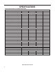


Table Of Contents
- INTRODUCTION
- Important Safety Information
- Personal Injury Or Death Hazards
- Operation of Equipment in During Construction
- Typical Unit Components and Dimensions
- Model Number Reference Guide
- Serial Number Reference Guide
- Product Features
- General Specifications 9-12k Heat Pump Models
- Electrical Data
- Function and Control
- Buttons and Display
- Temperature Definition
- System Basic Function
- 1) Cooling Mode
- 2) Heating Mode
- 3) Room Freeze Protection (AUTO HEATING)
- 4) Temperature Sensor Open Circuit or Short Circuit Protection
- 5) Power cut protection
- 6) Compressor and DC-inverter features
- 7) Smart fresh air system
- Advanced Functions
- Advanced Settings
- Memory Function
- FD Control (front-desk control) & 24V REMOTE THERMOSTAT
- Protection Functions
- System Configuration Fresh Air Vent Control
- Digital Control User Input Configuration
- Settings- Detailed Configurations
- Refrigeration Sequence Of Operation
- Refrigerant System Diagram
- PTAC Installation Recommendations
- Wall Sleeve Installation Instructions (PDXWS)
- Alternate Wall Installations
- PXDR10 Drain Kit Installation
- External Drain
- PXGA Standard Grille
- Chassis Install
- Remote Control Thermostat Installation
- Front Desk Control Terminal
- Final Inspection & Start-up Checklist
- Remove Chassis
- Remove User Interface
- Open Electrical Control Box
- Remove Main PCB (logic) Board
- Remove Power Cord
- Remove Power PCB
- Remove IPM PCB (Inverter Board)
- Remove Blower Wheel (Inside Fan)
- Remove Blower Wheel Motor (Inside Fan)
- Remove Heating Element
- Remove Freshaire Components
- Remove Outdoor Fan
- Remove Reversing valve Solenoid
- Refrigerant Charging
- Undercharged Refrigerant Systems
- Overcharged Refrigerant Systems
- Restricted Refrigerant System
- Sealed System Method of Charging/ Repairs
- Hermetic Components Check
- Reversing Valve Description And Operation
- Testing The Reversing Valve Solenoid Coil
- Checking The Reversing Valve
- Touch Test Chart : To Service Reversing Valves
- Compressor Checks
- Compressor Replacement
- Compressor Replacement -Special Procedure in Case of Compressor Burnout
- Check Indoor Fan Motor
- Check Outdoor Fan Motor
- Check Fan Motor Capacitors
- Main PCB (logic) Board Connector Identification
- Power PCB (Power Board) Connector Identification
- Basic Troubleshooting
- Error code and solutions
- Unit Does Not Operate
- Check Electric Heater Control
- Check Thermistors
- Check Thermistors -Resistance Table of Thermistors (5K)
- Check Thermistors -Resistance Table of Thermistors (50K)(Compressor Discharge Sensor)
- PARTS CATALOG

14 PB
SPECIFICATIONS
Electrical Data
13
GNINRA W
15/20A LCDI Device 30A LCDI Device
TEST BEFORE EACH USE
NO TTUB TESER SSERP .1
2. PLUG LCDI INT O POWER
ELCA TPECER
,NO TTUB TSET SSERP .3
RESET BUTTON SHOULD
POP UP
4. PRESS ,NO TTUB TSET
FOR USE
DO NOT TSET EVOBA FI ESU
SLIA F
WHEN GREEN LIGHT IS ON
IT IS WORKING PROPERL Y
RESET
TEST
GNINRA W
TEST BEFORE EACH USE
NO TTUB TESER SSERP .1
2. PLUG LCDI INT O POWER
ELCA TPECER
,NO TTUB TSET SSERP .3
RESET BUTTON SHOULD
POP UP
,NO TTUB TSET SSERP .4
FOR USE
DO NOT TSET EVOBA FI ESU
SLIA F
WHEN GREEN LIGHT IS ON
IT IS WORKING PROPERL Y
RESET
TEST
FRP014
A. Electrical Rating Tables
All 230/208 volt units are equipped with LCDI power cords.
All 265 volt units are equipped with non-LCDI power cords.
FUSE/CIRCUIT
BREAKER
Use ONLY type and size fuse or HACR cir-
cuit breaker indicated on unit’s rating plate.
Proper current protection to the unit is the
responsibility of the owner. NOTE: A time
delay fuse is provided with 265V units.
GROUNDING
Unit MUST be grounded from branch circuit
through service cord to unit, or through
separate ground wire provided on per-
manently connected units. Be sure that
branch circuit or general purpose outlet is
match plug on service cord and be within
reach of service cord. Refer to Table 1 for
proper receptacle and fuse type. Do NOT
alter the service cord or plug. Do NOT use
an extension cord.
RECEPTACLE
service cord and be within reach of service
cord. Refer to Table 1 for proper receptacle
and fuse type. Do NOT alter the service
cord or plug. Do NOT use an extension
cord.
All Friedrich 230/208V PTAC units are shipped from the factory with a
Leakage Current Detection Interrupter (LCDI) equipped power cord. The
LCDI device meets the UL and NEC requirements for cord connected air
conditioners effective August 2004.
To test your power supply cord:
1. Plug power supply cord into a grounded 3 prong outlet.
2. Press RESET.
3. Press TEST ( listen for click; Reset button trips and pops out).
4. Press and release RESET (listen for
click; Reset button latches
and remains in). The power supply cord is ready for operation.
NOTE: The LCDI device is not intended to be used as a switch.
Once plugged in the unit will operate normally without the need to reset
the LCDI device.
If the LCDI device fails to trip when tested or if the power supply cord is
damaged it must be replaced with a new supply cord obtained from the
product manufacturer, and must not be repaired.
B. Power Cord Information (230/208V models only)
Figure 14
Typical LCDI Devices
NOTE: Use Copper Conductors ONLY. Wire sizes are per NEC, check local codes for overseas applications.
WARNING
Electrical Shock Hazard
Turn off electrical power before service
or installation.
ALL electrical connections and wiring
MUST be installed by a qualified
electrician and conform to the National
Code and all local codes which have
jurisdiction.
Failure to do so can result in property
damage, personal injury and/or death.
RECEPTACLES AND FUSE TYPES
Voltage 230V 265V
Amps
15 20 30 15 20 30
Heater Size
2.5 kW 3.5 kW 5.0 kW 2.5 kW 3.5 kW 5.0 kW
Receptacles
NEMA#
Receptacle
6-15R 6-20R 6-30R 7-15R 7-20R 7-30R
NEMA#
Plug
6-15P 6-20P 6-30P 7-15P 7-20P 7-30P
Table 1