
Service and Parts Manual (2018, 2019, 2020, 2021, 2022)
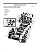


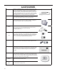


Table Of Contents
- INTRODUCTION
- Important Safety Information
- Personal Injury Or Death Hazards
- Operation of Equipment in During Construction
- Typical Unit Components and Dimensions
- Model Number Reference Guide
- Serial Number Reference Guide
- Product Features
- General Specifications 9-12k Heat Pump Models
- Electrical Data
- Function and Control
- Buttons and Display
- Temperature Definition
- System Basic Function
- 1) Cooling Mode
- 2) Heating Mode
- 3) Room Freeze Protection (AUTO HEATING)
- 4) Temperature Sensor Open Circuit or Short Circuit Protection
- 5) Power cut protection
- 6) Compressor and DC-inverter features
- 7) Smart fresh air system
- Advanced Functions
- Advanced Settings
- Memory Function
- FD Control (front-desk control) & 24V REMOTE THERMOSTAT
- Protection Functions
- System Configuration Fresh Air Vent Control
- Digital Control User Input Configuration
- Settings- Detailed Configurations
- Refrigeration Sequence Of Operation
- Refrigerant System Diagram
- PTAC Installation Recommendations
- Wall Sleeve Installation Instructions (PDXWS)
- Alternate Wall Installations
- PXDR10 Drain Kit Installation
- External Drain
- PXGA Standard Grille
- Chassis Install
- Remote Control Thermostat Installation
- Front Desk Control Terminal
- Final Inspection & Start-up Checklist
- Remove Chassis
- Remove User Interface
- Open Electrical Control Box
- Remove Main PCB (logic) Board
- Remove Power Cord
- Remove Power PCB
- Remove IPM PCB (Inverter Board)
- Remove Blower Wheel (Inside Fan)
- Remove Blower Wheel Motor (Inside Fan)
- Remove Heating Element
- Remove Freshaire Components
- Remove Outdoor Fan
- Remove Reversing valve Solenoid
- Refrigerant Charging
- Undercharged Refrigerant Systems
- Overcharged Refrigerant Systems
- Restricted Refrigerant System
- Sealed System Method of Charging/ Repairs
- Hermetic Components Check
- Reversing Valve Description And Operation
- Testing The Reversing Valve Solenoid Coil
- Checking The Reversing Valve
- Touch Test Chart : To Service Reversing Valves
- Compressor Checks
- Compressor Replacement
- Compressor Replacement -Special Procedure in Case of Compressor Burnout
- Check Indoor Fan Motor
- Check Outdoor Fan Motor
- Check Fan Motor Capacitors
- Main PCB (logic) Board Connector Identification
- Power PCB (Power Board) Connector Identification
- Basic Troubleshooting
- Error code and solutions
- Unit Does Not Operate
- Check Electric Heater Control
- Check Thermistors
- Check Thermistors -Resistance Table of Thermistors (5K)
- Check Thermistors -Resistance Table of Thermistors (50K)(Compressor Discharge Sensor)
- PARTS CATALOG

108 PB
APPENDIX
Reference Sheet of Celsius and Fahrenheit
Service Manual
Installation and Maintenance
52
Fahrenheit
display
temperature
(°F)
Fahrenheit
(°F)
Celsius(°C)
Fahrenheit
display
temperature
(°F)
Fahrenheit
(°F)
Celsius(°C)
Fahrenheit
display
temperature
(°F)
Fahrenheit
(°F)
Celsius(°C)
32/33 32 0 55/56 55.4 13 79/80 78.8 26
34/35 33.8 1 57/58 57.2 14 81 80.6 27
36 35.6 2 59/60 59 15 82/83 82.4 28
37/38 37.4 3 61/62 60.8 16 84/85 84.2 29
39/40 39.2 4 63 62.6 17 86/87 86 30
41/42 41 5 64/65 64.4 18 88/89 87.8 31
43/44 42.8 6 66/67 66.2 19 90 89.6 32
45 44.6 7 68/69 68 20 91/92 91.4 33
46/47 46.4 8 70/71 69.8 21 93/94 93.2 34
48/49 48.2 9 72 71.6 22 95/96 95 35
50/51 50 10 73/74 73.4 23 97/98 96.8 36
52/53 51.8 11 75/76 75.2 24 99 98.6 37
54 53.6 12 77/78 77 25
Appendix:
Appendix 1: Reference Sheet of Celsius and Fahrenheit
Conversion formula for Fahrenheit degree and Celsius degree: Tf=Tcx1.8+32
Set temperature
Ambient temperature
Fahrenheit
display
temperature
(°F)
Fahrenheit
(°F)
Celsius(°C)
Fahrenheit
display
temperature
(°F)
Fahrenheit
(°F)
Celsius
(°C)
Fahrenheit
display
temperature
(°F)
Fahrenheit
(°F)
Celsius
(°C)
61 60.8 16 69/70 69.8 21 78/79 78.8 26
62/63 62.6 17 71/72 71.6 22 80/81 80.6 27
64/65 64.4 18 73/74 73.4 23 82/83 82.4 28
66/67 66.2 19 75/76 75.2 24 84/85 84.2 29
68 68 20 77 77 25 86 86 30