
Service and Parts Manual (2018, 2019, 2020, 2021, 2022)
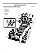


Table Of Contents
- INTRODUCTION
- Important Safety Information
- Personal Injury Or Death Hazards
- Operation of Equipment in During Construction
- Typical Unit Components and Dimensions
- Model Number Reference Guide
- Serial Number Reference Guide
- Product Features
- General Specifications 9-12k Heat Pump Models
- Electrical Data
- Function and Control
- Buttons and Display
- Temperature Definition
- System Basic Function
- 1) Cooling Mode
- 2) Heating Mode
- 3) Room Freeze Protection (AUTO HEATING)
- 4) Temperature Sensor Open Circuit or Short Circuit Protection
- 5) Power cut protection
- 6) Compressor and DC-inverter features
- 7) Smart fresh air system
- Advanced Functions
- Advanced Settings
- Memory Function
- FD Control (front-desk control) & 24V REMOTE THERMOSTAT
- Protection Functions
- System Configuration Fresh Air Vent Control
- Digital Control User Input Configuration
- Settings- Detailed Configurations
- Refrigeration Sequence Of Operation
- Refrigerant System Diagram
- PTAC Installation Recommendations
- Wall Sleeve Installation Instructions (PDXWS)
- Alternate Wall Installations
- PXDR10 Drain Kit Installation
- External Drain
- PXGA Standard Grille
- Chassis Install
- Remote Control Thermostat Installation
- Front Desk Control Terminal
- Final Inspection & Start-up Checklist
- Remove Chassis
- Remove User Interface
- Open Electrical Control Box
- Remove Main PCB (logic) Board
- Remove Power Cord
- Remove Power PCB
- Remove IPM PCB (Inverter Board)
- Remove Blower Wheel (Inside Fan)
- Remove Blower Wheel Motor (Inside Fan)
- Remove Heating Element
- Remove Freshaire Components
- Remove Outdoor Fan
- Remove Reversing valve Solenoid
- Refrigerant Charging
- Undercharged Refrigerant Systems
- Overcharged Refrigerant Systems
- Restricted Refrigerant System
- Sealed System Method of Charging/ Repairs
- Hermetic Components Check
- Reversing Valve Description And Operation
- Testing The Reversing Valve Solenoid Coil
- Checking The Reversing Valve
- Touch Test Chart : To Service Reversing Valves
- Compressor Checks
- Compressor Replacement
- Compressor Replacement -Special Procedure in Case of Compressor Burnout
- Check Indoor Fan Motor
- Check Outdoor Fan Motor
- Check Fan Motor Capacitors
- Main PCB (logic) Board Connector Identification
- Power PCB (Power Board) Connector Identification
- Basic Troubleshooting
- Error code and solutions
- Unit Does Not Operate
- Check Electric Heater Control
- Check Thermistors
- Check Thermistors -Resistance Table of Thermistors (5K)
- Check Thermistors -Resistance Table of Thermistors (50K)(Compressor Discharge Sensor)
- PARTS CATALOG

103 PB
ITEM PART
NUMBER
PART DESCRIPTION USED ON MODEL QTY
23.1 67812210 Reversing Valve Solenoid PVH09K3FA, PVH09K3FB, PVH12K3FA, PVH12K3FB 1
23.1 67812211 Reversing Valve Solenoid PVH09R3FA, PVH09R3FB, PVH12R3FA, PVH12R3FB 1
23.2 67812219 Four way valve (Does not include
solenoid)
ALL 1
24 67812126 CONDENSER COIL ALL 1
25 67808032 FAN SHROUD ALL 1
26 67808030 TOP SUPPORT BRACKET ALL 1
27 67812130 IPM PCB (Inverter Board) 803320590130 PVH09K3FA, PVH09R3FA 1
27 67812164 IPM PCB (Inverter Board) 803320890121 PVH12K3FA, PVH12R3FA 1
27 67812222 IPM PCB 9K (Inverter Board) Assembly PVH09K3FB, PVH09R3FB 1
27 67812223 IPM PCB 12K (Inverter Board) Assembly PVH12K3FB, PVH12R3FB 1
28 67812185 CLAPBOARD PVH09K3FA, PVH09K3FB, PVH12K3FA, PVH12K3FB 1
28 67812125 CLAPBOARD PVH09R3FA, PVH09R3FB, PVH12R3FA, PVH12R3FB 1
29 67808056 RIGHT CORNER POST ALL 1
30 67812121 COMPRESSOR PVH09K3FA, PVH09K3B, PVH09R3FA, PVH09R3B 1
30 67812160 COMPRESSOR PVH12K3FA, PVH12K3B, PVH12R3FA, PVH12R3B 1
31 67808015 SEAL BRACKET ALL 1
32 67812119 AIR GUIDE PLATE 1 ALL 1
32 67808034 BLOWER END PLATE ALL 1
33 67808070 INDOOR MOTOR PVH09K3FA, PVH09K3FB 1
33 67808083 INDOOR MOTOR PVH09R3FA, PVH09R3FB 1
33 67812105 INDOOR MOTOR PVH12K3FA, PVH12K3FB 1
33 67808093 INDOOR MOTOR PVH12R3FA, PVH12R3FB 1
34 67808003 INDOOR MOTOR MOUNT ALL 1
35 67808064 SEAL PLATE ALL 1
36 67812122 POWER CORD COVER ALL 1
37 67812153 POWER PCB (Power Board) PVH09K3FA, PVH12K3FA 1
37 67812208 POWER PCB (Power Board) PVH09K3FB, PVH09R3FB, PVH12K3B, PVH12R3FB 1
37 67812198 POWER PCB (Power Board) PVH09R3FA, PVH12R3FA 1
38 67812116 MAIN PCB (Logic Board) PVH09K3FA, PVH09R3FA, PVH12K3FA, PVH12R3FA 1
38 67812207 MAIN PCB (Logic Board) PVH09K3FB, PVH09R3FB, PVH12K3FB, PVH12R3FB 1
38.1 67808012 PCB STAND OFF ALL 1
39 67808006 ELECTRIC HEATER RELAYS ALL 1
40 67812184 24V TRANSFORMER PVH09K3FA, PVH09K3FB, PVH12K3FA, PVH12K3FB 1
40 67812192 24V TRANSFORMER PVH09R3FA, PVH09R3FB, PVH12R3FA, PVH12R3FB 1
41 67812117 POWER CORD CONNECTOR ALL 2
42 67808063 POWER CORD FASTENER ALL 1
43 67812183 POWER CORD COVER ALL 1
44 67808008 ELECTRICAL BOX BOTTOM COVER ALL 1
45 67812115 ELECTRICAL BOX COVER ALL 1
Figure 901
PARTS CATALOG
PVH09K3FA, PVH09K3FB, PVH09R3FA, PVH09R3FB
PVH12K3FA, PVH12K3FB, PVH12R3FA, PVH12R3FB