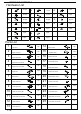
PRODUCT ASSEMBLY Hardware List A B C D E F G 6*35mm 28 pcs H 3 pcs O 28 pcs I 6 pcs P 20 pcs J 34 pcs Q 52 pcs K 8 pcs R 6 pcs L 2 pcs S 4 pcs M 2 pcs 6 pcs N 15*10mm 6*30mm 3*12mm 3*14mm 4*30mm 4*40mm 2.
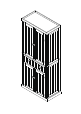
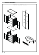
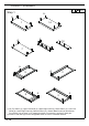
PRODUCT ASSEMBLY Part List Assembly Overview 24 1 2 22 4 22 5 6 15 3 15 23 23 6 7 25 8 10 11 15 12 15 9 16 20 13 21 14 19 2/12 18 17 21
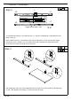
PRODUCT ASSEMBLY A Step 1 A A 1 14 A A 18 A 19 7 A A 9 8 A 3 2 A 1) Lay Top Panel (1), Upper Left Panel (2), Upper Right Panel (3), Divide Panel (7), Lower Left Panel (8), Lower Right Paenl (9), Bottom Panel (14), Drawer Back Panel (18) and Drawer Front Panel (19) as shown on a material that does not scratch the surface of each part. 2) Screw in Cam-bolt (A) into the designated holes on each in clockwise direction.
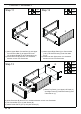
PRODUCT ASSEMBLY Step 2 L L L2 2 pcs L1 L1 L2 X2 Trigger Disconnect Lever To install Drawer Glide (L), the Glide Runner (L1) needs to be detached or separated from the Glide Track (L2). Detach Glide Runner (L1) from Glide Track (L2) by sliding out (L1) from (L2) until the Trigger Disconnect Lever is visible on (L1) as shown above. Next, depress the Trigger Disconnect Lever and at the same time slide out (L1) from (L2).
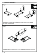
PRODUCT ASSEMBLY Step 4 D D I D I 13 D 22 pcs I 6 pcs K 8 pcs D D D I K D 6 K K D X2 12 K Attach Hinge (K) and Magnetic Bar (I) to Upper Door (6), Lower Left Door (12) and Lower Right Door (13) with Screw (D) as shown. Step 5 D 4 pcs L2 2 pcs D L2 8 9 Attach Drawer Glide (L2) to Lower Left Panel (8) and Lower Right Panel (9) with Screw (D) as shown.
PRODUCT ASSEMBLY Step 6 B 17 21 21 16 19 B 8 pcs C 4 pcs F 4 pcs 20 C F 1) Attach Drawer Left Panel (16), Drawer Right Panel (17) and Drawer Connect Bar (21) to Drawer Front Panel (19) via Wood Dowel (C) and Cam-bolts on (19). 2) Insert Cam-lock (B) and turn it in clockwise direction to lock onto Cam-bolts. 18 B 3) Insert Drawer Bottom Panel (20). C 4) Attach Drawer Back Panel (18) via Wood Dowel (C) and Cam-bolts on (18). 5) Insert Screw (F) and tighten it.
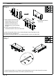
PRODUCT ASSEMBLY Step 8 B 2 pcs C 2 pcs Step 9 B 2 pcs C 2 pcs 8 B 11 c 9 11 B c 10 10 c 1) Attach Lower Top Connect Bar (10) and Lower Middle Connect Bar (11) to Lower Left Panel (8) via Wood Dowel (C) and Cam-bolts on (8). 2) Insert Cam-lock (B) and turn it in clockwise direction to lock onto Cam-bolts. 1) Attach Lower Right Panel (9) to Connect Bar (10 & 11) via Wood Dowel (C) and Cam-bolts on (9). 2) Insert Cam-lock (B) and turn it in clockwise direction to lock onto Cam-bolts.
PRODUCT ASSEMBLY Step 11 B 2 pcs C 2 pcs Step 12 2 C 4 B B 4 B 2 pcs C 2 pcs 3 C 5 5 1) Attach Upper Back Connect Bar (4) and Upper Front Connect Bar (5) to Upper Left Panel (2) via Wood Dowel (C) and Cam-bolts on (2). 2) Insert Cam-lock (B) and turn it in clockwise direction to lock onto Cam-bolts. 1) Attach Upper Right Panel (3) to Connect Bar (4 & 5) via Wood Dowel (C) and Cam-bolts on (3). 2) Insert Cam-lock (B) and turn it in clockwise direction to lock onto Cam-bolts.
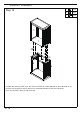
PRODUCT ASSEMBLY Step 14 B 4 pcs N 2 pcs P 4 pcs 2 3 7 P B N 10 8 9 1) Attach the unit from STEP 13 to the unit From STEP 10 via Wood Dowel (P) and Cam-bolts on (7). 2) Insert Cam-lock (B) to (8 & 9) and turn it in clockwise direction to lock onto Cam-bolts. 3) Fix Connect Bar (10) to (7) with Screw (N).
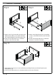
PRODUCT ASSEMBLY Step 15 J 17 pcs J 17 pcs J 22 24 23 25 1) Attach Upper Back Panel (22) and Lower Back Panel (23) with Screw (J). 2) Insert Upper Back Connect Bar (24) to (22). 3) Insert Lower Back Connect Bar (25) to (23). Step 16 24 22 J 22 22 25 23 23 23 1) Slide Upper Back Panel (22) and Lower Back Panel (23) as per the groove on Back Connect Bar (24 & 25). 2) Fix the Back Panel (22 & 23) with Screw (J).
PRODUCT ASSEMBLY Step 17 S 6 D R 6 16 pcs G 2 pcs O 2 pcs 4 pcs 4 pcs D 2 6 3 8 12 9 1) Attach Upper Door (6) to Upper Left and Right Panel (2 & 3) with Screw (D). 2) Attach Lower Left and Right Door (12 & 13) to Lower Left and Right Panel (8 & 9) with Screw (D). 3) Attach Knob (S) to Door with Knob Bolt (R). 13 WALL Step 18 D R S O G 1) Drill two holes in the dry wall per the length and diameter of Plastic Anchor (O).
PRODUCT ASSEMBLY Q Step 19 Q Insert Shelf Pin (Q) and place Adjustable Shelf (15) on it. 15 Step 20 Insert Drawer.