Boost Charger ™ DC Fast Charging Station Site Preparation Guide Version 1.
Copyright and trademarks ©2014-2020 FreeWire Technologies, Inc. All rights reserved. This material is protected by the copyright laws of the United States and other countries. It may not be modified, reproduced or distributed without the prior, express written consent of FreeWire Technologies, Inc. FREEWIRE, FREEWIRE TECHNOLOGIES, AMP and BOOST CHARGER are U.S. registered trademarks and service marks of FreeWire Technologies, Inc. and cannot be used without the prior written consent of FreeWire®.
Safety and compliance The FreeWire Boost Charger is for Outdoor Use Only and to be mounted on a non-combustible surface such as a concrete pad that extends a minimum of 3 feet beyond the perimeter of the battery system/Boost Charger. The Boost Charger should comply with all local and national codes and standards and only be installed by a licensed contractor and a licensed electrician. It is the site owner’s responsibility to comply with all local codes and safety laws.
This page is left intentionally blank
Boost Charger DC Fast Charging Station Site Preparation Guide Version 1.0 Table of Contents GENERAL WARNINGS................................................................................................................................ 6 1 INTRODUCTION.................................................................................................................................... 7 Boost Charger Overview.....................................................................................................
Symbols used in this site preparation guide WARNING: This indicates a fact or feature very important for the safety of the user to prevent injury or death and/or which can cause serious hardware damage if not applied appropriately. CAUTION: Identifies information to prevent damage to this product. GROUND: Earth ground symbol. General Warnings SHOCK RISK: HIGH VOLTAGE ELECTRICITY. WARNING: To reduce the risk of injury, read all instructions and caution markings before installing the FreeWire Boost Charger.
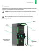
1 INTRODUCTION 1 Introduction This guide describes how to prepare your installation site for the FreeWire® Boost Charger™ DC fast charger. Read this document first to become familiar with the details and ensure that you have all the necessary tools and materials to prepare the Boost Charger Concrete Mounting Pad. Important: Always check local codes or consult an engineer to ensure that the site is prepared in compliance with all applicable codes.
1 INTRODUCTION Before You Start Check the cellular strength at the installation site before beginning. The Boost Charger communicates using a cellular network. FreeWire recommends that the signal is -110 dBm or better. Install repeaters if the signal is too low or if the signal is intermittent. You can measure signal strength using a signal meter device, or by initiating a strength test using a field test mode on your smartphone. Instructions for this differ by smartphone, carrier, and operating system.
1 INTRODUCTION Lightning Protection In geographic areas that experience frequent thunderstorms, it is recommended to install one electrode (ground rod) near the Boost Charger foundation. This is dependent on the local regulations and should be determined by the contractor. It may be necessary to consult a local specialist for the options of lightning protection.
1 INTRODUCTION Concrete Mounting Template The Mounting Template ships separately, prior to the Boost Charger. Please contact FreeWire to coordinate. The site must be prepared by running conduit and building a concrete mounting pad. Use the FreeWire Technologies Boost Charger Concrete Mounting Template (820-00255-01) for the mounting pad. The mounting template will correctly align the mounting bolts and conduit to ensure that the Boost Charger can be easily positioned.
2 PREPARING THE MOUNTING PAD 2 Preparing the Mounting Pad This section provides instructions on how to prepare the mounting pad. Overview of Steps • Run the Conduit and Cable (page 11) • Assemble the Mounting Template (page 12) • Install the Mounting Template (page 16) Run the Conduit and Cable Boost Charger service wiring must be installed underground by means of conduit in compliance with local electrical codes. When calculating the grade, type, and size of the conduit, consult local codes.
2 PREPARING THE MOUNTING PAD Assemble the Mounting Template Conduit Feed *dimensions are in inches 12
2 PREPARING THE MOUNTING PAD The AC conduit enters the opening from the front of the Boost Charger. Follow the steps below to assemble the mounting template: Press the plastic cap fully down onto the bolt 3.8” Concrete surface Distance should be 2.3” Hold the bottom washer and nut against the top surface of the bottom plate while adjusting the bolt Step 1 Insert one bolt into one of the bolt holes of the top plate of the template.
2 PREPARING THE MOUNTING PAD Mounting Specifications Stay out zones and maintenance access points are indicated by hashed lines. The following details are all shown in inches. Bollard locations are recommendations only and should be determined based on the site selection, local codes, and ADA constraints.
2 PREPARING THE MOUNTING PAD Vehicle Impact Protection Important: When installing bollards or other barriers, be sure to verify the stay out zones identified in the mounting specifications on page 14. It is recommended to protect the Boost Charger against vehicle impact damage when located in the path of a vehicle or in a parking lot. Check with local and state codes or the International Fire Code® (IFC®) to see if the installation of the Boost Charger will require bollards.
2 PREPARING THE MOUNTING PAD Install the Concrete Mounting Template Dig an opening to accommodate the wiring conduit and the concrete mounting pad. Step 1 Excavate the site making room for the concrete foundation pad that meets local codes and requirements. Step 2 Construct a concrete form for the concrete foundation pad. Important: Make sure that the conduit is positioned within 1/16” of the opening in the mounting template and is plumb. The conduit should extend 8.0” above the concrete surface.
3 BOOST CHARGER SPECIFICATIONS 3 Boost Charger Specifications System Max Output Power CHAdeMO: 100 kW CCS: 120 kW Combined: charge two vehicles up to 60 kW each Max Output Current CHAdeMO: 200 A CCS: 300 A Dimensions 40 in x 43 in x 96 in Weight 3,800 lbs Output Voltage, Charging 200 VDC – 500 VDC Electrical Input Input Rating 240 (+/- 10%) VAC, split-phase, 4-Wire, 120 A, 60 Hz 208 (+/- 10%) VAC 3-phase, WYE, 5-Wire, 80 A 60 Hz Wiring For 240 V - 2 conductors (L1, L2) Ground For 208 V - 4
3 BOOST CHARGER SPECIFICATIONS Safety and Compliance Safety Compliance U.S.: complies with UL 2202, UL 2231-1, UL 2231-2, UL 991, UL 1973 (battery pack) EMC Compliance U.S.: FCC part 15 Class A Safety: Electric Vehicle • See the EV supplier’s guide for proper care of the EV and follow directions carefully. Failure to follow EV care instructions can results in EV explosion and property damage, severe injury, or death during charging. • Do not disconnect charger connector while the EV is charging.
NOTES 19
www.freewiretech.com Any additional questions please contact: (415) 484-9590 support@freewiretech.com 1933 Davis St. Suite 301A San Leandro, CA 94577 Boost Charger Site Preparation Guide v1.0. 8.24.