Boost Charger ™ DC Fast Charging Station Operating and Maintenance Manual Version 1.
Copyright and trademarks ©2014-2020 FreeWire Technologies, Inc. All rights reserved. This material is protected by the copyright laws of the United States and other countries. It may not be modified, reproduced or distributed without the prior, express written consent of FreeWire Technologies, Inc. FREEWIRE, FREEWIRE TECHNOLOGIES, AMP and BOOST CHARGER are U.S. registered trademarks and service marks of FreeWire Technologies, Inc. and cannot be used without the prior written consent of FreeWire®.
Safety and compliance The FreeWire Boost Charger is for Outdoor Use Only and to be mounted on a non-combustible surface such as a concrete pad that extends a minimum of 3 feet beyond the perimeter of the battery system/Boost Charger. The Boost Charger should comply with all local and national codes and standards and only be installed by a licensed contractor and a licensed electrician. It is the site owner’s responsibility to comply with all local codes and safety laws.
This page is left intentionally blank
Boost Charger DC Fast Charging Station Operating and Maintenance Manual Version 1.0 Table of Contents 1 1.1 2 3 4 5 T F INTRODUCTION.................................................................................................................................... 6 Overview............................................................................................................................................................. 6 A R D OPERATING THE BOOST CHARGER...................................
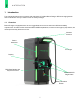
1 INTRODUCTION 1 Introduction This manual describes how to operate and maintain the FreeWire Boost Charger DC fast charging station and is intended for use by a station owner or facility manager. 1.1 Overview Boost Charger is equipped with a 24-inch ruggedized touch screen that meets ADA accessibility requirements. A credit card terminal with NFC and RFID capabilities, as well as an emergency stop button, are located prominently below the screen.
2 OPERATING THE BOOST CHARGER 2 2.1 Operating the Boost Charger Powering on the Boost Charger There is an emergency stop button, however there is no separate on/off switch for the Boost Charger. Note: The emergency stop button should not be used as an on/off switch. The Boost Charger fast charging station is powered on during the installation by energizing the site’s electrical panel.
2 OPERATING THE BOOST CHARGER 2.4 Configure System Behavior The site manager and/or station operator has the ability to customize a number of the Boost Charger software features. These include: • Setting pricing for electric vehicle (EV) drivers • Set different pricing/access policies for different groups To configure or make changes to settings at any time, log in to your EV Connect Administrator Portal by visiting https://ops.evconnect.
2 OPERATING THE BOOST CHARGER Step 9 Return the cable to the charging station holster. Step 10 Tap ‘Exit’ to return to the home screen. Note: The driver may select to plug in the vehicle first, then initiate charging on the screen. This is also supported by the Boost Charger (Plug, Pay, Go). 2.6 LED Status Indicators The LED Status Indicators will change depending on availability and/or status of the charger. • Solid Green - Available for charging. • Blinking Green - Charging session initiating.
3 USER INTERFACE WALK-THROUGH 3 User Interface Walk-through 3.1 3.1.1 Getting Started Home Screen The Boost Charger home screen has four major components to welcome the user. Two panels on the far left and right sides of the screen specify the charger type, CHAdeMO and/or CCS, and availability. The ‘Help’ and ‘Pricing Details’ buttons on the bottom of the screen help you decide which connector to use and provides details on the cost per charge.
3 USER INTERFACE WALK-THROUGH 3.2 Payment 3.2.1 Payment Options After selecting connector type, users can either (a) tap an EV Connect RFID card, if they have one, or (b) insert/swipe/tap a credit card on the reader available directly below the screen. ‘Pricing Details’ can be accessed on this page for more information on charging rates. This pricing table is also accessible on the home screen.
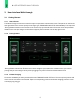
3 USER INTERFACE WALK-THROUGH 3.4 Active Charging 3.4.1 Charging Screen When charging is in progress, charging information will be displayed on the side of the screen that corresponds with the active connector. Information includes: • Current charge: Vehicle battery charge in percentage. • Time elapsed: Time elapsed since charging was initiated in minutes and seconds. • Energy delivered: Energy delivered to the vehicle in kilowatt-hours (kWh).
3 USER INTERFACE WALK-THROUGH 3.5 DUAL CHARGING Boost Charger can charge up to two EVs at once. Follow the steps below for instructions on how to connect and charge a second vehicle. 3.5.1 Select Connector not in Use The connector not in use will display the message “Available for charging”. Select the panel for the available charger to initiate the charging process. 3.6 3.6.1 STOP CHARGING Stop Charging Charging can be stopped at any time.
3 USER INTERFACE WALK-THROUGH 3.6.2 Charging Stopped A charging stopped confirmation screen will appear the end of the charging session. It is now safe to remove the connector from the vehicle. Tapping the ‘Exit’ button will return to the home screen. 3.7 Driver Support If a user experiences any issues with using the Boost Charger, please contact EV Connect at (866) 816-PLUG.
4 BOOST CHARGER MAINTENANCE 4 4.1 Boost Charger Maintenance Maintenance Overview The FreeWire Boost Charger is designed for minimal maintenance over its lifetime. The network connection monitors the health of the system as well as any error codes or faults. An alert is sent when corrective maintenance or service might be required. The Boost Charger Warranty includes preventative maintenance for the duration of the selected warranty.
4 BOOST CHARGER MAINTENANCE 4.3 Preventative Maintenance Preventative maintenance is included in the Boost Charger warranty. FreeWire Technologies or FreeWire approved personnel should perform all service checks as defined below. DANGER: RISK OF ELECTRIC SHOCK. No user serviceable parts inside. Only authorized personnel may service this equipment. To reduce the possibility of injury, turn main disconnect switch “OFF” and padlock before servicing equipment.
5 BOOST CHARGER SPECIFICATIONS 5 Boost Charger Specifications System Max Output Power CHAdeMO: 100 kW CCS: 120 kW Combined: charge two vehicles up to 60 kW each Max Output Current CHAdeMO: 200 A CCS: 300 A Dimensions 40 in x 43 in x 96 in Weight 3,800 lbs Output Voltage, Charging 200 VDC – 500 VDC Electrical Input Input Rating 240 (+/- 10%) VAC, split-phase, 4-Wire, 120 A, 60 Hz 208 (+/- 10%) VAC 3-phase, WYE, 5-Wire, 80 A 60 Hz Wiring For 240 V - 2 conductors (L1, L2) Ground For 208 V - 4
5 BOOST CHARGER SPECIFICATIONS Safety and Compliance Safety Compliance U.S.: complies with UL 2202, UL 2231-1, UL 2231-2, UL 991, UL 1973 (battery pack) EMC Compliance U.S.: FCC part 15 Class A Safety: Electric Vehicle • See the EV supplier’s guide for proper care of the EV and follow directions carefully. Failure to follow EV care instructions can results in EV explosion and property damage, severe injury, or death during charging. • Do not disconnect charger connector while the EV is charging.
NOTES 19
www.freewiretech.com Any additional questions please contact: (415) 484-9590 support@freewiretech.com 1933 Davis St. Suite 301A San Leandro, CA 94577 Boost Charger Operating and Maintenance Manual v1.0. 8.28.