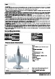
Note A NOTE: This is not a toy. Not for children under 14 years. Young people under the age of 14 should only be permitted to operate this model under the instruction and supervision of an adult. Please keep these instructions for further reference after completing model assembly. 1.This is not a toy! Operate should have a certain experience, beginners should operate under the guidance of professional players. 2.
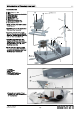
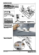
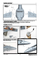
Introduction of Fuselage rear part Accessories list: A Screw (Ping. isi dos) B-Serra C Wood piece for elevator servo Installation D Elevator drive shaft 1 E Elevator drive shaft 2 F Elevator control horn @Jim sower chits zoos) Sore (Faz 3x8 pus) 1 Elevator drive shaft fixing part 1 J Elevator drive shaft fling part 2 K-Sower (waists zoos) * 1.Firstly, operate your radio to center the servo am. 2.Install the servo on the "wood piece (CY. fixed it by “screw 3.
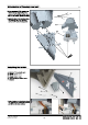
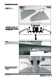
Introduction of Fuselage rear part 2.If you purchased PNP version, you need to loosen “screw and remove “rear fuselage bottom-foam If KIT version, ignore this step.)| Paws dam) 3.Apply the glue to the indicated place, and adhesive the “rear fuselage up-foam (F)” to the “fuselage Installing the rudder A Rudder fixing plastic part B Screw (pages apes) C Screw (assize pes) D Screw traits isms) E Rear fuselage bottom-foam F Rudder 1.
Installing the rudder 1.Install the “Led light (G)* on ths rudder, then uss slug to adhesive the “LED cover (F)" on the rudder. fom £ a pests sm 2.Buckle the "LED light ina {H)" into “rough {IY". 3.Apply the glue to the Indicated place, adhesive the “servo box (E)" on the rudder, then Install the ‘derv (C)° on the “servo box then fix the “servo cover (B)" on the “servo box (E)" by 2 pos “screw (AY. after these work, wa finished to fix the servo. 4.Then press the “servo cable (D)" In tha “trough I)".
Installing the elevator A Elevator set B Screw (rrs«e post ee Ba feign sp) 1" 1.As the right photo shown, insert + the "elevator set (A)" into the ! elevator drive shaft, and fix It by PCs “screws Fl {Ninth apo) 2.Use PCs scows to fix the rear fuselage bottom-foam on the fuselage.
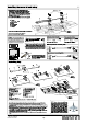
Installing the servo of main wing 1.Apply the glue on tha indicated place, and a upward fm ‘adhesive the “servo box (E)" on the man wing. oe Then install the “servo (C)" on the"servo box (EV u “craw (AY to fix the “larva cover (BY on the "servo box EY", after these work, ws finished to fix the servo. 2.
Installing scale weapons pylons A-Main wing B Scale weapons pylons A C-Gus 1.Apply the glue to the Indicated place, and adhesive the "scale ‘weapon pylons (BY on the bottom -surface of main wing. Note: wan we spin ths give, t ant to Walt ons minute, then begin the nonabrasive. This time, the EPO glue 5 the strongest adhesive condition. Within son minutes after adhesive, wa must repast fo aqueous the adhesive surfaces, It wil he wore firmly.
Installing main wing A-sower (Fiddled Apes) B servo cable G Wing carbon tubs Fuselage bolt 1.Insert the wing carbon tube into the fuselage, but don’t need to close. Then connect the “servo cable, LED cable (B)” and the extension line in fuselage. 2.Close the main wing and fuselage, and use “screw (A)” to screw the bolt, to finish this step. 3.Repeat above steps to install another side main wing. Installing nose cone 1.Firstly, use slug to adhesive the nose cone on the fuselage. 2.
Installing nose landing gear Usually, before ship, the factory installed all the landing gear. In here, we also need to provide mare details installation and spare part name. Players can refer it to revise and replace parts.
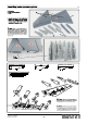
Installing rear landing gear r landing gear spare part list: 1 Light cover J Taxi light K-Pin LE-buckle (1 5) M-Wheel N-Wheel gear O-Jim screw tw) P Pin Q-Sower use spiny 1.Insert the “rear landing gear metal wire (C) Into “landing gear rotating arm and use PCs “Mimi screws (BY to fix. 2.Connect the “rear landing gear main strut (D)" and “rear landing gear metal wire by pin and “E-buckle”. 3.
Installing cabin door of rear landing gear A-Man cable door of rear landing gear BS ids cabin door of rear landing gear 1 C Side cabin door of rear landing gear 2 D -Push rod Enshroud F-Push rod Next, we Introduced how to Install the rear cabin door please refer to tha following steps to maintain and replace 1. Usa hand to squeeze Inward the “main cabin door of rear landing gear (A) and “side cabin door of rear landing C)" and made It curved.
Installing air brake A-Brake am B-Al brake rotating shaft ~~ C-Straw (
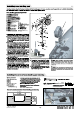
Install on battery " Lift up tape to remove the canopy, then bundled battery with Velcro. Before connect battery and receiver, please switch on the transmitter and check that the throttle is in the low position. The connector we connected with battery and ESC, is Our standard battery Is: 68 22.2V 5000mAh 35C You can choose the battery refer to the battery cabin size: L=176mm: W=75mm: H=55mm XT150 connector, its max current is 150A, please do not w 68 22.2V4800mAh 6000mAh overload to use.
Install power system 1. Put tha “motor (B)” into “dusted fan housing Use PCs “cup head screw (D)” to fix the motor. Put the “blade (E)" into motor shaft. {Please note the plat position of hardware which Installed In the fan,and the plat position of motor shaft, please check the alignment to install together) Put the “spinner on the “blade Use “cup head screw (G)" to fix the “blade (E)" on the motor shaft. Put the "glued cons (A) In the “bottom of motor and use 2 pcs “Jim screw {H)" to fix.
Control direction test After installed the plane, before flying, we need a fully charged battery and connect to the ESC, then use radio to test and check that every control surface work properly.
Troubleshooting Guide Motor does not turn on A) Li-Po battery depleted B) Transmitter batteries depleted ©) Transmitter not muted an A) Recharge LI-Po battery B) Replace or recharge batteries ©) Tum an transmitter D) Li-Po battery not plugged In D) Plug In Li-Po battery E} Motor not armed E} Arm motor F) Crash has damaged an Intestinal component G) ESC or other damaged F} Replace 6) Hack ESC or contact local distributor Cub is difficult to control A) You are flying In tao much wind B) Li-Po battery depleted