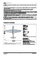
Note: AN NOTE: This is not 2 toy. Not for children under 14 years. Young people under the age of 14 should only be permitted to operate this model under the Instruction and supervision of an adult, Please keep these Instructions for further reference after completing model assembly, 1.This is not a toy! Operate should have a certain experience, beginners should operate under the guidance of professional players. 2.
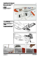
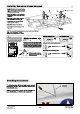
Installing tail wing set Firstly, wo dean to remove these accessories from package: A Elevator B Rudder C Rudder fixed plastic part D Screw poesy 1.Use craw {D} to fix the elevator (A) on the rear of fuselage. 2.Insert the rudder (B} to the rear of fuselage, and turn over the fuselage. 3.Use rudder fixed plastic part (C) and screw (D) to fix the rudder. LZ ba (ma2.
Installing tail wing set A Rudder Servo Elevator Servo Finish te install the rudder and elevator, we need to center the control surface of rudder and elevator firstly, then begin to do the next step. Since after finish to install main wing, it will cover the elevator and rudder, not easy to operate. 1.Remove the plastic (A). Before removing, pull the plastic part up firstly, and press the side of plastic part (A), let the buckle aut, then remove the plastic parts. 2.
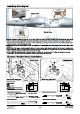
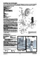
Installing Main Wing Set Please refer to the following to Install main wing. Prepare these accessories list: Firefighting wing B-carbon tube C-Wire D-LED light controller E-Landing gear cabin sequencer F-man wing fixed plastic place 1 G-man wing fixed plastic piece 2 H-screw 1.Connect left/right wing (A) by carbon tube (B} 2.Before close left/right wing, please refer to “ serve/LED light/ retracts connection diagram, connect the Y wire (C), LED light controller {D}, Landing gear cabin sequencer (E). 3.
Installing main wing set 4.Turn over the fuselage, put the man wing near the fuselage, then Insert the cable of " rear retract and rear retract cabin” Into “landing gear cabin sequencer”. finish to connect all the cable, adhesive the LED light controller {D) and landing gear cabin sequencer (E} to the cabin wall. 6.At last, buckle the main wing into fuselage, use main wing fixed plastic piece 1 (F) and main wing fixed plastic piece 2 (G} and PCs screws (H) to fix the main wing.
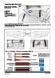
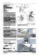
Installing the servo of main wing set 1.As the right photo shown, apply the glue ‘tithe Indicated place, and adhesive the 17g servo box (B) and control surface hom (A) to the main wing. 2.Press the 17g servo in the servo box, also press the servant cabs (G) Ina the trough (H). 3. Putthe servo cover on the servo box (B), and fix it by 2 pes screws (E). 4.Connect the servo arm and control ‘surface horn by push rod. the allusion to be centered. 6.According to the above steps, install flap servo.
Installing Propeller Before install propeller, we need to install the PCs blades together. A-Spinner B-Propeller fixed disk C-Blade D-Screw (pizzicati pos) E-Screw (Pus dps} F-Nut #3 &pce G-Nut m8 pest H-Gasket 1. Atfirst, put the nut (F) on the back of hexagonal hole of propeller fixed disk (B). 2.Then Install the blade (C} on the propeller fixed disk (B) ‘and fix it by screw (D). 3.Repeat 1,2 two steps, to finish all the blades Installation. Installing Propeller 1.
Installing nose landing gear In here, we introduce for you how to install the landing gear? If it happen any problem, you can refer to the following to revise. At the same time, you can choose correct spare parts to purchase from local distributor and replace it. Nose landing gear accessories list A-Landing gear electric base B-Jim screw (hiss) ad F.U shape damping arm G Spring.
Recur landing gear accessories Hat: A-Landing gear electric base B E-bucks (82.6) C Screw Trina D L-shape steering arm staring control ring gear staring push rod G Rear landing gear plastic decorated part H Rear landing gear main metal wire 1-Wheel J Screw 0 K-Wheel shock L Rear landing gear sst M Screw (52.210) N Rear gear mount 1. Atfirst, disassemble the Landing gear electric bass (A), ‘and remove the rear landing gear rotating arm. 2.
Connection diagram of scale engine sound system Speaker Amplifier board lama, Connection line vd (Soundcheck backcomb snd “Recant) Install on battery Lift up taps, It irremovable canopy Scala snuggles sound system Lift up tape, it removable canopy, then bundled battery with Velcro. Our standard power system battery is : 48 14.8V 2200mAh 35C = Our standard Scale engine sound system battery is : Before connect battery and receiver, please switch 38 11.
Center of Gravity Correct center of gravity is directly related to the success of the flight, please refer to the following CG diagram to adjust your plane's center of gravity. You can move the battery forward or backward to adjust the center of gravity. If you can not adjust the CG through move the battery, you can also use some other suitable material weight to counterweight, to make sure that CG is in the correct position.
Control surface direction and set up After installed the plane, before flying, we need a fully charged battery and connect to the ESC, then use radio to test and check that every control surface work properly.
Troubleshooting Guide Motor does not turn on A) Li-Po battery depleted B) Transmitter batteries depleted ©) Transmitter not muted an A) Recharge LI-Po battery B) Replace or recharge batteries ©) Tum an transmitter D) Li-Po battery not plugged In D) Plug In Li-Po battery E} Motor not armed E} Arm motor F) Crash has damaged an Intestinal component G) ESC or other damaged F} Replace 6) Hack ESC or contact local distributor Cub is difficult to control A) You are flying In tao much wind B) Li-Po battery depleted