
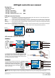
Lighting Controller User Manual

LED light controller
Item No.: E01
Version No.: V3
LED light controller user manual
- LED light controller
- Output lines
- LED light red(0.06W) 2pcs
- LED light green(0.06W) 2pcs
- LED light white(0.06W)
- LED light white(3W with light cover) 3pcs
1pcs
8pcs
LED light controller Function
Input A ---------------
Input voltage 3.7~4.5V,and connect it to the landing gear cabin sequencer. Then landing gear cabin
sequencer will provide power and signal source.
light 1-----------------
Connect with 3-5W high light LED light, no flashing, constant light, use for the take-off light of model plane.
light 2-----------------
Connect with less than 0.1W light LED light, "light 2"include the three output ports, no flashing, constant light.
Flashing-------------
Connect with less than 0.1W light LED light, ”Flashing” include four output ports,LED light will be flashing
according to the set frequency.
Flash Frequency--
Flash Frequency mainly use for the ”Flashing” channel.Clockwise rotation, will accelerate the LED lights
flashing frequency, counterclockwise rotation, will slow down LED lights flashing frequency.
Package list
S + -
+ -
+ -
V3
s
+
Light
Flashing
+
Light
1
2
Flashing Light
Light
1
2
+
Flash Frequency
+
LED light
controller
Landing gear cabin
sequencer
V
Multi-function
s
+
2
+
S + -
+ -
+ -
V3
s
+
Light
Flashing
+
Light
1
2
+
Flash Frequency
+
LED light
controller
Light
1
3W High LED light
Light
2
0.6W Continuous LED light
Flashing
0.6W Flashing LED light
Light
1
3W High LED light
Light
2
0.6W Continuous LED light
Flashing
0.6W Flashing LED light
S + -
+ -
+ -
V3
s
+
Light
Flashing
+
Light
1
2
Input A
(Power/signal input)
Input A
(Power/signal input)
Input A
(Power/signal input)
+
Flash Frequency
+
LED light
controller
LED controller connection drawing
Note: When all the LED light connected, under working for sustained, the working current is <1A. Before you install the airplane, you should
ensure your ESC to have enough extra current to support LED light controller, If not, it may cause the damage of ESC or electric part.
Version 1
Version 2
Receiver
(Retract Channel)
Receiver
(Retract Channel)
If you also have the Landing gear cabin sequencer, as the
above diagram shown, after connect the LED light into LED
light controller, Input A connect into the landing gear cabin s
equencer. At last, insert the landing gear cabin sequencer into
the landing gear channel of receiver.
If you only have the LED light controller, after
LED light connection, Input A can insert into
the landing gear channel of receiver directly.
Under this circumstance, the landing gear
channel of radio will control the 3W LED light
switch on/off of Light 1.
Landing gear cabin sequencer