F-B6 SRBRE USER mRnURL somm EDF .
Product basic information 2 Package list 3 Installing fuselage 3 Installing elevator 4 Installing main wing 5 Installing rudder 6 Installing the nose landing gear 7 Nose landing gear cabin door installation 8 Rear landing gear installation 9 Servo introduction 9 Install on battery 10 Install power system 10 Motor parameters 11 Center of gravity 12 Control surface direction and set up 13 Dual rates 13 Elevator installing angle 14 Troubleshooting guide 16 16 17 17 18 19 20 21 22 23 23 24 24 25 26 27 27 28
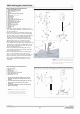
Introduction C Thank you for purchasing our first 80 mm EDF, the North American F-86 Sabre! Orignally designed and intended for the Air Force in 1944 with the designation NA-134, the aircraft had straight wings and a rather fat fuselage with an axial flow engine. Ultimately, the NA-134 went to the Navy as the XFJ-1 Fury, which was the first fighter they had ever ordered from North American .
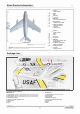
Basic Product Information EN Motor .. J:a, en en Ill :I C. Ill "'I C. � "'I UI 0 :I 3525-2870KV ESC BOA Servos 9g (8pcs) • Battery 4S 14.8V 4000mAh 35C Ducted fan 6-Bladed 80mm EDF Take-off weight 1950g (68.72 oz.) Thrust 1900g (67 oz.) Motor O') en C "C cc "'I Ill C. CD _____ 1200mm (47.24 in) ------...i ,& Note: The parameters stated here are derived from test results using our accessories. If you use other accessories, the test results will differ.
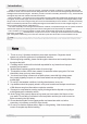
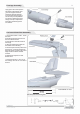
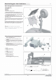
Fuselage Assembly EN Apply glue to the rods and join the tail section to the fuselage. More glue can be applied to the two sections as deemed necessary. For best results, allow the glue to become tacky, then separate the two pieces so that the glue forms strings, and rejoin. Repeat three times then permanently join the two sections. Horizontal Stabilizer Assembly 1 . Using a servo tester or radio, center the servo. 2.Use the supplied glue to secure the servo into the servo hatch. 3.
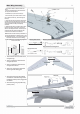
Main Wing Assembly EN 1. Use a servo tester or radio to center the servo. �A PWA1.7x5 2. Use the supplied glue to secure the servo box (E) into the servo hatch. T/t 3. Install servo (C) into the servo box(E). B 4. Use 2 screws (A) to screw the servo cover (B) to the servo hatch (E), thus securing the servo(C). 5.
Rudder Assembly EN 1. Center the servo arm with either a servo tester or your radio. 2. Insert the servo box (E) into the cavity in the vertical stabilizer. 3. Install the servo (C) inside the servo box (E). 4. Using 2 screws (A), fasten the servo cover (B) to the servo box which will secure the servo to the Stabilizer. 5. Thread the open end of the control rod into the servo arm and adjust the clevis so that the rudder is in the neutral position when it is attached. 23.8mm 23.8mm PWA 1. 7x5 A =:::::::.
Nose Gear Assembly The F86 has two versions: the 4S standard version and the 6S upgrade Version. The 4S version uses metal landing gear, the 6S uses a full Aluminum damping landing gear. We also provide the full aluminum damping landing gear as a spare part, so you can upgrade to the 4S version. The following is an exploded diagram of the two landing gears for reference.
Nose landing gear door installation EN Nose landing gear door accessories list A- Nose gear door 1 B - Nose gear door 2 C - Metal wire D-Spring E - Pushrod F - Gear door installing mount 1. Install the metal ball head on the"nose gear door 1 (A)". 2. Use "metal wire (C)" to connect the "nose cabin door 1 (A)" and "nose cabin door 2 (B)". then bend the end of "metal wire (C)" to secure it. 3.
Main landing gear installation EN Rear landing gear accessories list Full aluminum damping landing gear instructions A- Main landing gear metal pin B - Main landing gear main strut C -Grub screw (M4•3mm) ·--- J D- Spring E - Rear landing gear damping shaft F- Pin G- Rear wheel (050'16mm) ��E H - Metal spacer I - Wheel shaft J - Grub screw (M3•3mm) K - Assembled main landing gear set L- Grub screws (M3•3mm) M- Landing gear electric retract G N - Assembled landing gear ,.,.
Servo introduction EN A servo or reversed servo is defined as follows: When the servo input signal changes from 1000ųs to 2000ųs, if the servo arm rotates clockwise, it's a positive servo. If it rotates counter clockwise, it's a reversed servo. I If you decide to purchase another brand of servo, refer to the following list to ensure that it is correct type and size . Servo installing position Servo No. Pos./Rev.
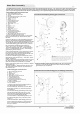
Power system Installation 1.Put the motor (D) in the ducted fan housing (C). 2.Secure the motor with 4 cup head screws (B). 3.Put the rotor (E) in the motor shaft. ( During this process, please note the hardware platform of rotor should be in alignment with the motor shaft platform) 4.Use spinner (F) to cover the rotor, and secure the spinner (F) with a cup-head-screw (G). 5.Install the tail air-deflector (A) to the bottom of ducted fan housing (C), and use 2 Grub screws (H) to secure it. 6.
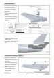
Center of Gravity EN Correct center of gravity is directly related to the success of the flight, please refer to the following CG diagram to adjust your plane's center of gravity. - You can move the battery forward or backward to adjust the center of gravity. - If you can not adjust the CG by moving the bat t ery, you can also use some other suitable material weight to counterweight. - It is extremely important to ensure that CG is in the correct position.
Control surface direction and set up EN After the build is complete , power up the radio and connect a fully charged battery to the ESC. Use the radio to ensure correct control direction. Ailerons Stick Left Stick Right Elevator Stick Back Stick Forward Rudder Stick Left Stick Right Optional Flaps Flaps Down F-86 Sabre Item No.: FJ2031 Version No.
Dual Rates EN According to our test results, the following rates proved to be a good starting point. Low rates are good for initial flights or less experienced pilots. High Rates will be more sensitive to control inputs After initial flights, adjust the rates to suit your own style. Ailerons Flaps Elevator Rudder H1 1---- -I--- H2 _J____ 1 , L---Jl.
Troubleshooting Guide Motor does not run Airplane is difficult to control A) Li-Po battery depleted A) Recharge Li-Po battery B) Transmitter batteries depleted B) Replace or recharge batteries C) Transmitter not turned on C) Turn on transmitter D) Li-Po battery not plugged in D) Plug in Li-Po battery E) Motor not armed E) Arm motor F) A crash has damaged an internal component F) Replace G) ESC may be damaged G) Check ESC or contact local distributor A) You are flying in too much wind A) Fl
@,ccWMg Dongguan Freewing Electronic Technology Ltd HK Freewing Model International Limited Add.:FeiYi Building.face to Labor Bureau, Fumin Middle Road, Dalang Town, Dongguan City , Guangdong Province, China Web: http://www.sz-freewing.com Email:freewing@sz-freewing.com Fax:86-769-82033233 Tel: 86-769-82669669 ffi�$�K�rf411��R0.§J � � � tltj� 00 �;"[\� �R 0 .§J :l:-f!!M:: 1*�*�m-Jc�A�'M � i=J=i�402-408%"E.Jf� [Y� Web: http://www.sz-freewing.com Email:freewing@sz-freewing.