
Reference Manual
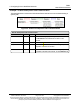
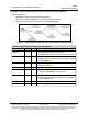

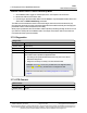
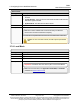
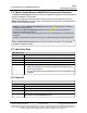
Table Of Contents
- Preface
- 1. Introduction
- 2. Basic Radio Programming and Setup
- 2.1. Setting the Radio's Role in the Network and the Network Type
- 2.2. Establishing Communication with Instrumentation and Computers
- 2.3. Establishing Communication with Other Radios in the Network
- 2.4. Designate the RF Transmission Characteristics
- 2.4.1. 900MHz Channel Select Parameters
- 2.4.2. 900MHz Frequency Key (Golden Setting)
- 2.4.3. 900MHz Frequency Zones
- 2.4.4. High Noise
- 2.4.5. 900MHz Hop Frequency Offset
- 2.4.6. 900MHz Hop Table Size
- 2.4.7. 900MHz Hop Table Version
- 2.4.8. Max Packet Size and Min Packet Size (Golden Setting)
- 2.4.9. MCU Speed
- 2.4.10. Remote LED
- 2.4.11. Retry Time Out
- 2.4.12. RF Data Rate (Golden Setting)
- 2.4.13. RTS to CTS
- 2.4.14. Slave Security
- 2.4.15. Transmit Power
- 2.4.16. Transmit Rate
- 3. Configuring Point-to-MultiPoint Networks
- 3.1. Point to MultiPoint Network Characteristics
- 3.2. Point-to-MultiPoint Network Quick Start
- 3.3. Point-to-MultiPoint Operation LEDs
- 3.4. Overlapping MultiPoint Networks
- 3.5. Establishing Communication with Other Radios in a MultiPoint Network
- 3.6. Routing Communications through the Network
- 3.7. Setting Other MultiPoint Parameters
- 3.7.1. 1 PPS Enable Delay
- 3.7.2. Diagnostics
- 3.7.3. DTR Connect
- 3.7.4. Local Mode
- 3.7.5. Master Packet Repeat
- 3.7.6. Master Packet Repeat in MultiPoint Networks with Repeaters
- 3.7.7. Max Slave Retry
- 3.7.8. Radio ID
- 3.7.9. Radio Name
- 3.7.10. Repeaters
- 3.7.11. Repeater Frequency
- 3.7.12. Retry Odds
- 3.7.13. Slave / Repeater
- 3.8. Conserving Power
- 3.9. Reading Diagnostics in Tool Suite
- 4. Configuring Point-to-Point Networks
- 5. Advanced Programming
- 6. Viewing Radio Statistics
- 7. Approved Antennas
- 8. FGR3 Wireless Data Radios Pinouts
- 9. Troubleshooting
- 10. FGR3 Release Notes
- Appendix A: FGR3 Technical Specifications
- Appendix B: FGR3 Board Level Mechanical Drawing
- Appendix C: 900MHz Factory Default Settings
- Appendix D: 900MHz Channel Frequency IDs
- Appendix E: FreeWave Legal Information

3. Configuring Point-to-MultiPoint Networks
FGR3
User-Reference Manual
LUM0110AA Rev Jan-2019 Page 75 of 143 Copyright © 2019FreeWave
This document is subject to change without notice. This document is the property of FreeWave Technologies, Inc.
and contains proprietary information owned by FreeWave. This document cannot be reproduced in whole or in
part by any means without written permission from FreeWave Technologies, Inc.
Example 3: Subnet and Optional Slave Communication
This example shows:
l Repeater 1 must talk directly to the Master.
l Repeater 2 must talk directly to Repeater 1.
l Slave 1, 2, and 3 are forced along the direction of the solid lines.
l Slave 4 may link to the first Master or Repeater it hears in the network.
Figure 22: Subnet and Optional Slave Communication
Subnet and Optional Slave Communication
Radio Rx Tx Additional Information
Master 0 or F 0 or F The default settings (F, F) actually use 0, 0.
The Rx Subnet on the Master has no effect on the
network.
Repeater 1 0 1 Rx Subnet = 0 forces the radio to link only to the Master.
Repeater 2 1 2 Rx Subnet = 1 forces communication through Repeater 1.
Repeater 1 transmits on SubnetID 1.
Slave 1 0 0 or F Rx Subnet = 0 forces communication through the Master.
Slave 2 1 0 or F Rx Subnet = 1 forces communication through Repeater 1.
Slave 3 2 0 or F Rx Subnet = 2 forces communication through Repeater 2.
Slave 4 0 0 The 0, 0 setting allows the Slave to link with the:
l first Master or
l Repeater it hears with the same Network ID.