
Reference Manual

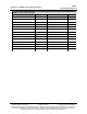
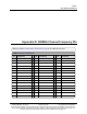
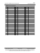
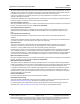

Table Of Contents
- Preface
- 1. Introduction
- 2. Basic Radio Programming and Setup
- 2.1. Setting the Radio's Role in the Network and the Network Type
- 2.2. Establishing Communication with Instrumentation and Computers
- 2.3. Establishing Communication with Other Radios in the Network
- 2.4. Designate the RF Transmission Characteristics
- 2.4.1. 900MHz Channel Select Parameters
- 2.4.2. 900MHz Frequency Key (Golden Setting)
- 2.4.3. 900MHz Frequency Zones
- 2.4.4. High Noise
- 2.4.5. 900MHz Hop Frequency Offset
- 2.4.6. 900MHz Hop Table Size
- 2.4.7. 900MHz Hop Table Version
- 2.4.8. Max Packet Size and Min Packet Size (Golden Setting)
- 2.4.9. MCU Speed
- 2.4.10. Remote LED
- 2.4.11. Retry Time Out
- 2.4.12. RF Data Rate (Golden Setting)
- 2.4.13. RTS to CTS
- 2.4.14. Slave Security
- 2.4.15. Transmit Power
- 2.4.16. Transmit Rate
- 3. Configuring Point-to-MultiPoint Networks
- 3.1. Point to MultiPoint Network Characteristics
- 3.2. Point-to-MultiPoint Network Quick Start
- 3.3. Point-to-MultiPoint Operation LEDs
- 3.4. Overlapping MultiPoint Networks
- 3.5. Establishing Communication with Other Radios in a MultiPoint Network
- 3.6. Routing Communications through the Network
- 3.7. Setting Other MultiPoint Parameters
- 3.7.1. 1 PPS Enable Delay
- 3.7.2. Diagnostics
- 3.7.3. DTR Connect
- 3.7.4. Local Mode
- 3.7.5. Master Packet Repeat
- 3.7.6. Master Packet Repeat in MultiPoint Networks with Repeaters
- 3.7.7. Max Slave Retry
- 3.7.8. Radio ID
- 3.7.9. Radio Name
- 3.7.10. Repeaters
- 3.7.11. Repeater Frequency
- 3.7.12. Retry Odds
- 3.7.13. Slave / Repeater
- 3.8. Conserving Power
- 3.9. Reading Diagnostics in Tool Suite
- 4. Configuring Point-to-Point Networks
- 5. Advanced Programming
- 6. Viewing Radio Statistics
- 7. Approved Antennas
- 8. FGR3 Wireless Data Radios Pinouts
- 9. Troubleshooting
- 10. FGR3 Release Notes
- Appendix A: FGR3 Technical Specifications
- Appendix B: FGR3 Board Level Mechanical Drawing
- Appendix C: 900MHz Factory Default Settings
- Appendix D: 900MHz Channel Frequency IDs
- Appendix E: FreeWave Legal Information

Appendix E: FreeWave Legal Information
FGR3
User-Reference Manual
LUM0110AA Rev Jan-2019 Page 142 of 143 Copyright © 2019FreeWave
This document is subject to change without notice. This document is the property of FreeWave Technologies, Inc.
and contains proprietary information owned by FreeWave. This document cannot be reproduced in whole or in
part by any means without written permission from FreeWave Technologies, Inc.
Important!: Antenna types not included in this list, having a gain greater than the maximum gain indicated
for that type, are strictly prohibited for use with this device.
Les types d'antenne non inclus dans cette liste, et dont le gain est supérieur au gain maximal indiqué, sont
strictement interdits pour l'exploitation de l'émetteur.
Approved Antennas List
Approved Antennas List
Antenna Type
Maximum Gain
(dBi)
Impedance
(Ohms)
Yagi Directional 8.6 50
Omni-directional 8.15 50
GNU License Notification
Some of the software in the firmware is licensed under the GNU General Public License and other Open Source
and Free Software licenses. Contact FreeWave to obtain the corresponding source on CD.
UL Notifications / Warnings - Class1 Div2
Warning! EXPLOSION HAZARD! - Substitution of components may impair suitability for Class 1,
Division 2.
Warning! DO NOT REMOVE or insert the diagnostics cable while the circuit is live!
UL Power Source
Input voltage for the listed models is +6.0 to +30.0 VDC.
Important!: Input power shall be derived from a certified, Class 2 power source.
Do not connect or disconnect any connectors while the circuit is live unless the area is known to be non-
hazardous.
Warning! The FGR3-WC model described in this User Manual is NOT UL certified.
l Models FGR3-C-U, FGR3-CE-U, and FGR3-T-U are suitable for use in Class 1, Division 2, Groups A, B,
C, and D or non-hazardous locations only.
Schedule of Limitations
l Provision shall be made to prevent the rated voltage being exceeded by the transient disturbances of more
than 140% of the peak rated voltage.
l The system shall be mounted in an ATEX certified enclosure with a minimum ingress protection rating of at
least IP54 as defined in EN60529 and used in an environment of not more than pollution degree 2.
l The enclosure must have a door or cover accessible only by the use of a tool.
l Ambient Temperature -40°C to +75°C.
l Supply conductors should be a minimum 85°C.