
Reference Manual
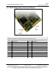
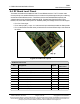
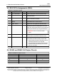


Table Of Contents
- Preface
- 1. Introduction
- 2. Basic Radio Programming and Setup
- 2.1. Setting the Radio's Role in the Network and the Network Type
- 2.2. Establishing Communication with Instrumentation and Computers
- 2.3. Establishing Communication with Other Radios in the Network
- 2.4. Designate the RF Transmission Characteristics
- 2.4.1. 900MHz Channel Select Parameters
- 2.4.2. 900MHz Frequency Key (Golden Setting)
- 2.4.3. 900MHz Frequency Zones
- 2.4.4. High Noise
- 2.4.5. 900MHz Hop Frequency Offset
- 2.4.6. 900MHz Hop Table Size
- 2.4.7. 900MHz Hop Table Version
- 2.4.8. Max Packet Size and Min Packet Size (Golden Setting)
- 2.4.9. MCU Speed
- 2.4.10. Remote LED
- 2.4.11. Retry Time Out
- 2.4.12. RF Data Rate (Golden Setting)
- 2.4.13. RTS to CTS
- 2.4.14. Slave Security
- 2.4.15. Transmit Power
- 2.4.16. Transmit Rate
- 3. Configuring Point-to-MultiPoint Networks
- 3.1. Point to MultiPoint Network Characteristics
- 3.2. Point-to-MultiPoint Network Quick Start
- 3.3. Point-to-MultiPoint Operation LEDs
- 3.4. Overlapping MultiPoint Networks
- 3.5. Establishing Communication with Other Radios in a MultiPoint Network
- 3.6. Routing Communications through the Network
- 3.7. Setting Other MultiPoint Parameters
- 3.7.1. 1 PPS Enable Delay
- 3.7.2. Diagnostics
- 3.7.3. DTR Connect
- 3.7.4. Local Mode
- 3.7.5. Master Packet Repeat
- 3.7.6. Master Packet Repeat in MultiPoint Networks with Repeaters
- 3.7.7. Max Slave Retry
- 3.7.8. Radio ID
- 3.7.9. Radio Name
- 3.7.10. Repeaters
- 3.7.11. Repeater Frequency
- 3.7.12. Retry Odds
- 3.7.13. Slave / Repeater
- 3.8. Conserving Power
- 3.9. Reading Diagnostics in Tool Suite
- 4. Configuring Point-to-Point Networks
- 5. Advanced Programming
- 6. Viewing Radio Statistics
- 7. Approved Antennas
- 8. FGR3 Wireless Data Radios Pinouts
- 9. Troubleshooting
- 10. FGR3 Release Notes
- Appendix A: FGR3 Technical Specifications
- Appendix B: FGR3 Board Level Mechanical Drawing
- Appendix C: 900MHz Factory Default Settings
- Appendix D: 900MHz Channel Frequency IDs
- Appendix E: FreeWave Legal Information

8. FGR3 Wireless Data Radios Pinouts
FGR3
User-Reference Manual
LUM0110AA Rev Jan-2019 Page 115 of 143 Copyright © 2019FreeWave
This document is subject to change without notice. This document is the property of FreeWave Technologies, Inc.
and contains proprietary information owned by FreeWave. This document cannot be reproduced in whole or in
part by any means without written permission from FreeWave Technologies, Inc.
8.4. RF Board Level Pinout
The board-level radios are available in both TTL and RS232 versions. The TTL version uses
reverse polarity from standard RS232 at 0 to 5 Volt levels. All pin descriptions and pin numbering
are the same as the RS232 version. The RS232 version uses standard RS232 polarity and
voltage levels for all of the RS232 signal lines (DTR, Transmit Data, Receive Data, Carrier
Detect, RTS, and Clear to Send) and TTL standard polarity and voltage level for the Interrupt pin.
l Pin 1: B+ Power input.
l Pin 2: Interrupt (INT) – Input – A 0 Volt level on this pin switches the radio into Setup mode.
l Pin 1 on the board-level radio is the pin farthest from the three LEDs and pin 10 is closest to
the LEDs.
Figure 28: FGR3 Pin Layout
RF Board Level Pinout
Pin Assignment Signal
ACS3610xx
Cable Color
1 B+ input Power Red
2 Interrupt (temporarily ground to invoke menu) Input Brown
3 Data Terminal Ready (DTR) Input Orange
4 Ground Black
5 Transmit Data (TXD) Output Yellow
6 Ground Black
7 Receive Data (RXD) Input Green
8 Carrier Detect (DCD) Output Blue
9 Request to Send (RTS) Input Violet (purple)
10 Clear to Send (CTS) Output Gray