
Installation Manual

FreeWave Technologies I-Series User Manual Addendum
Installation Manual
V1.0a
5
B.2. “Mobile Mark” SCR14-2400 antenna.
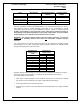
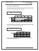
Table B.2.1 below shows how the RFXmitPower settings on the radio correspond to the EIRP
of the transceiver-cable-antenna combination for the SCR14-2400 antenna at different cable
loss values if the communication system is Point-to-Multipoint.
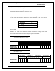
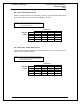
Table B.2.2 below shows how the RFXmitPower settings on the radio correspond to the EIRP
of the transceiver-cable-antenna combination for the SCR14-2400 antenna at different cable
loss values if the communication system is Point-to-Point.
Shaded area indicates combinations where EIRP limitations exceed FCC regulations
and RF Xmit Power must be reduced.
Table B.2.1: EIRP for SCR14-2400 Antenna, Cable loss vs
“RFXmit Power” Setting for Point-to-Multipoint
systems.
Cable Loss
1dB 2dB 3dB 4dB
5 dB
RF Xmit
9
40.00 39.00 38.00 37.00 36.00
Power
8
39.50 38.50 37.50 36.50 35.50
7
38.75 37.75 36.75 35.75 34.75
6
37.50 36.50 35.50 34.50 33.50
5
35.50 34.50 33.50 32.50 31.50
Table B.2.2: EIRP for SCR14-2400 Antenna, Cable loss vs
“RFXmit Power” Setting for Point-to-Point
systems.
Cable Loss
1dB 2dB 3dB 4dB
RF Xmit
9
40.00 39.00 38.00 37.00
Power
8
39.50 38.50 37.50 36.50
7
38.75 37.75 36.75 35.75
6
37.50 36.50 35.50 34.50
5
35.50 34.50 33.50 32.50