
Data Sheet

Software Setup
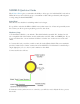
The six output channels on the N-Drive Shield are connect to 6 digital outputs on your Arduino.
The outputs are biased off by default, and can be turned on by driving the matching output
HIGH.
Digital Control
Even a simple example such as Blink can be used simply by changing the pin. This slightly
modified version of Blink allows you to easily change the selected output to test your N-Drive
Shield:
int output_pin = 3;
void setup() {
pinMode(output_pin, OUTPUT);
}
void loop() {
digitalWrite(output_pin, HIGH); // turn the output on (HIGH is the voltage level)
delay(1000); // wait for a second
digitalWrite(output_pin, LOW); // turn the output off by making the voltage LOW
delay(1000); // wait for a second
}
Open the Arduino IDE, and either open an existing example (such as File -> Examples ->
01.Basics -> Blink) and modify it to suit, or create a new sketch and paste in the code above.
Compile and upload it to your Arduino.
The status LEDs on the N-Drive Shield provide handy visual feedback even when you don't have
any loads connected, making it very easy to check that your program is doing the right thing.
PWM (Analog) Control
The specific pins have been selected because they support PWM (Pulse Width Modulation) on
typical Arduino boards, which allows you to drive loads partially on. This is perfect for high-
power LEDs, particularly RGB LEDs.
The "Fading" example included with the Arduino IDE is perfect for testing this functionality.
Open File -> Examples -> 02.Analog -> Fading, upload it to your Arduino, and watch the result
on the status LED