
Data Sheet


2
2
6
6
This document is the exclusive property of GlobalTop Tech Inc. and should not be distributed, reproduced, into any other format without
prior permission of GlobalTop Tech Inc. Specifications subject to change without prior notice.
Copyright © 2011 GlobalTop Technology Inc. All Rights Reserved.
F
G
PMMOPA6H
Dat
a Sheet
GlobalTop Technology
Ver. V0
A
Document #
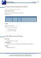
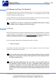
4. Reference Design
This chapter introduces the reference schematic design for the best performance. Additional tips
and cautions on design are well documented on Application Note, which is available upon request.
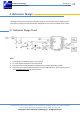
4.1 Reference Design Circuit
Note:
1. Ferrite bead L1 is added for power noise reduction.
2. C1 and C2 bypass should be put near the module.
3. Damping resistors R2,R3,R4 could be modified based on system application for EMI.
4. If you need more support and information on antenna implementation, please directly contact
us at sales@gtop-tech.com for further services.