
Data Sheet

1
1
5
5
This document is the exclusive property of GlobalTop Tech Inc. and should not be distributed, reproduced, into any other format without
prior permission of GlobalTop Tech Inc. Specifications subject to change without prior notice.
Copyright © 2011 GlobalTop Technology Inc. All Rights Reserved.
F
G
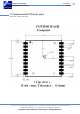
PMMOPA6H
Dat
a Sheet
GlobalTop Technology
Ver. V0
A
Document #
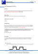
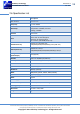
After 2D or 3D Fix
The pin should continuously output low-level signal.
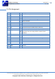
NC (Pin6, Pin7, Pin15, Pin16, Pin17, Pin18, Pin20)
Not connect.
TX (Pin9)
This is the UART transmitter of the module. It outputs the GPS information for application.
RX (Pin10)
This is the UART receiver of the module. It is used to receive software commands and firmware
update.
EX_ANT (Pin11)
DC power from VCC and provide for external active antenna (Recommendation: 3.3V).
When a 4mA or higher current is detected, the detect circuit will acknowledge the external antenna
as being present and uses external antenna for reception.
In the event of short circuit occurring at external antenna, the module will limit the drawn current to
a safe level.
The 3.0V for the GPS external antenna is limited to 25mA.
The 3.3V for the GPS external antenna is limited to 28mA.
The 3.6V for the GPS external antenna is limited to 31mA.
1PPS (Pin13)
This pin provides one pulse-per-second output from the module and synchronizes to GPS time.
Keep floating if not used.
RTCM (Pin14)
This pin receive DGPS data of RTCM protocol (TTL level), if not used keep floating’
RTCM is not enabled by default, please consult GlobalTop support to enable this feature.
Low