
Target Interface User Manual


Installation
Configuring the Platform Board
2–11MMDS0508 Target Interface
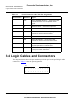
Figure 2.2 M68MMDS0508 Station Module (Left Side)
2.2 Configuring the Platform Board
The MMDS platform board has four jumper headers, all located near the front. Jumper
header J1 is for factory test. Jumper headers J2, J3, and J4 control the voltage levels
for ports A through D.
NOTE
Before shipping the MMDS, factory personnel configure the
platform board correctly for virtually all users. You should not
reconfigure platform-board headers unless your EM user’s manual
tells you to.
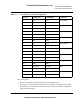
2.2.1 Factory Test Header (J1)
The diagram in Figure 2.3 shows the factory configuration of jumper header J1. The
jumper between pins 1 and 2 is correct for MMDS operation.
Panel
+5V Out
Power Switch
9-Pin Serial
Power Cord
Socket
Connector
Freescale Semiconductor, Inc.
For More Information: www.freescale.com