
Board Users Guide


MPC5200B Users Guide, Rev. 1
20-22 Freescale Semiconductor
Functional Description
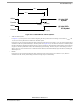
The min and max symbol limits shown in the following sections (Invalid Passive Bit - Valid BREAK Symbol) and figures (Figure 20-6 -
Figure 20-9) refer to the values listed in Table 20-13 throughTable 20-18.
• Invalid Passive Bit
If the passive to active transition beginning the next data bit or symbol occurs between the active to passive transition beginning the
current data bit or symbol and T
rvp1(Min)
, the current bit would be invalid. See Figure 20-6(1).
Figure 20-6. J1850 VPW Passive Symbols
• Valid Passive Logic Zero
If the passive to active transition beginning the next data bit or symbol occurs between T
rvp1(Min)
and T
rvp1(Max)
, the current bit
would be considered a logic zero. See Figure 20-6(2).
• Valid Passive Logic One
If the passive to active transition beginning the next data bit or symbol occurs between T
rvp2(Min)
and T
rvp2(Max)
, the current bit
would be considered a logic one. See Figure 20-6(3).
• Valid EOD Symbol
If the passive to active transition beginning the next data bit or symbol occurs between T
rvp3(Min)
and T
rvp3(Max)
, the current symbol
would be considered a valid EOD symbol. See Figure 20-6(4).
T
rvp1(Min)
T
rvp2(Min)
T
rvp2(Max)
T
rvp1(Max)
T
rvp1(Min)
(1) Invalid Passive
(2) Valid Passive
(3) Valid Passive
64µs
128µs
T
rvp3(Min)
T
rvp3(Max)
(4) Valid EOD
Symbol
Logic One
Bit
Logic Zero
200µs
Active
Passive
Active
Passive
Active
Passive
Active
Passive