
Board Users Guide


MPC5200B Users Guide, Rev. 1
20-20 Freescale Semiconductor
Functional Description
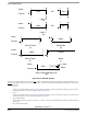
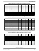
5 Start of Frame (SOF) T
tva3
198 200 202 t
bdlc
6 End of Data (EOD)
1
T
tvp3
162 164 166 t
bdlc
7 End of Frame (EOF)
1
T
tv4
238 240 242 t
bdlc
8 Inter-Frame Separator (IFS)
1
T
tv5
298 300 302 t
bdlc
Note:
1. The transmitter timing for this symbol depends upon the minimum detection time of the symbol by the receiver.
Table 20-14. BDLC Transmitter VPW Symbol Timing for Binary Frequencies
Number Characteristic Symbol Min Typ Max Unit
1 Passive Logic 0 T
tvp1
65 67 69 t
bdlc
2 Passive Logic 1 T
tvp2
132 134 136 t
bdlc
3 Active Logic 0 T
tva1
132 134 136 t
bdlc
4 Active Logic 1 T
tva2
65 67 69 t
bdlc
5 Start of Frame (SOF) T
tva3
208 210 212 t
bdlc
6 End of Data (EOD)
1
T
tvp3
170 172 174 t
bdlc
7 End of Frame (EOF)
1
T
tv4
250 252 254 t
bdlc
8 Inter-Frame Separator (IFS)
1
T
tv5
313 315 317 t
bdlc
Note:
1. The transmitter timing for this symbol depends upon the minimum detection time of the symbol by the receiver.
Table 20-15. BDLC Receiver VPW Symbol Timing for Integer Frequencies
Number Characteristic Symbol Min Typ Max Unit
1
Passive Logic 0 T
rvp1
32 64 95 t
bdlc
2 Passive Logic 1 T
rvp2
96 128 163 t
bdlc
3 Active Logic 0 T
rva1
96 128 163 t
bdlc
4 Active Logic 1 T
rva2
32 64 95 t
bdlc
5 Start of Frame (SOF) T
rva3
164 200 239 t
bdlc
6 End of Data (EOD) T
rvp3
164 200 239 t
bdlc
7 End of Frame (EOF) T
rv4
240 280 299 t
bdlc
8 Inter-Frame Separator (IFS) T
rv5
281 --- --- t
bdlc
9 Break Signal (BREAK) T
rv6
240 --- --- t
bdlc
Note:
1. The receiver symbol timing boundaries are subject to an uncertainty of 1 t
bdlc
due to sampling considerations.
Table 20-13. BDLC Transmitter VPW Symbol Timing for Integer Frequencies (continued)
Number Characteristic Symbol Min Typ Max Unit