
Board Users Guide


Functional Description
MPC5200B Users Guide, Rev. 1
Freescale Semiconductor 19-33
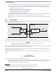
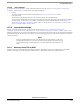
• Time Segment 2: This segment represents the PHASE_SEG2 of the CAN standard. It can be programmed by setting the TSEG2
parameter to be 2 to 8 time quanta long.
Figure 19-8. Segments within the Bit Time
The Synchronization Jump Width
1
can be programmed in a range of 1 to 4 time quanta by setting the SJW parameter.
The above parameters are set by programming the MSCAN Bus Timing Registers (CANBTR0, CANBTR1) (see Section 19.5.3, MSCAN
Control Register 0 (CANCTL0)—MBAR + 0x0900 / 0x980 and Section 19.5.6, MSCAN Bus Timing Register 1 (CANBTR1)—MBAR + 0x0905
/ 0x985).
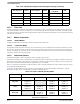
Table 19-34 gives an overview of the CAN compliant segment settings and the related parameter values.
NOTE
It is the user’s responsibility to ensure the bit time settings are in compliance with the CAN standard.
Table 19-33. Time Segment Syntax
Syntax Description
SYNC_SEG System expects transitions to occur on the bus during this period.
Transmit Point A node in transmit mode transfers a new value to the CAN bus at this
point.
Sample Point A node in receive mode samples the bus at this point. If the three
samples per bit option is selected, then this point marks the position
of the third sample.
1. Reference the Bosch CAN 2.0A/B protocol specification dated September 1991 for bit timing.
Table 19-34. CAN Standard Compliant Bit Time Segment Settings
Time Segment 1 TSEG1 Time Segment 2 TSEG2
Synchronization
Jump Width
SJW
5 .. 10 4 .. 9 2 1 1 .. 2 0 .. 1
4 .. 11 3 .. 10 3 2 1 .. 3 0 .. 2
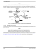
Bit Rate
f
Tq
number of Time QuantaÞÞ Þ()
-----------------------------------------------------------------------------------------=Þ
SYNC_SEG
Time Segment 1 Time Segment 2
1 4 ... 16 2 ... 8
8 ... 25 Time Quanta
= 1 Bit Time
NRZ Signal
Sample Point
(single or triple sampling)
(PROP_SEG + PHASE_SEG1) (PHASE_SEG2)
Transmit Point