
Board Users Guide


MPC5200B Users Guide, Rev. 1
18-14 Freescale Semiconductor
I
2
C Interface Registers
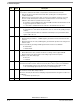
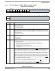
Bit Name Description
0ENI
2
C Enable—bit controls software reset of entire I
2
C module.
If I
2
C module is enabled in the middle of a byte transfer, interface behaves as follows:
• Slave mode ignores current bus transfer and starts operating when a subsequent start
condition is detected.
• Master mode is not aware if bus is busy. If a start cycle is initiated, current bus cycle may
become corrupt. Ultimately this results in the current bus master or I
2
C module losing
arbitration, after which bus operation returns to normal.
0 = module is reset and disabled. This is the Power-ON reset. When low the interface is held
in reset, but registers can still be accessed.
1 = I
2
C module is enabled. Bit must be set before other CR bits have any effect.
1IENI
2
C Interrupt Enable
0 = Interrupts from I
2
C module are disabled. This does not clear currently pending interrupt
condition.
1 = Interrupts from I
2
C module are enabled. An I
2
C interrupt occurs, provided the status
register IF bit is also set.
2 STA Master/Slave mode select—bit clears on reset.
• When bit changes from 0 to 1, a START signal is generated on the bus and master mode is
selected.
• When bit changes from 1 to 0, a STOP signal is generated and operation mode changes from
master to slave.
STA is cleared without generating a STOP signal when the master loses arbitration.
0 = Slave Mode
1 = Master Mode
3 TX Transmit/Receive mode select—bit selects master/slave transfer direction.
• When addressed as slave, software should set according to status register SRW bit.
• When in master mode, bit should be set according to type of transfer required.
For address cycles, bit is always high.
0 = Receive
1 = Transmit
4 TXAK Transmit Acknowledge enable—bit specifies value driven to SDA during acknowledge cycles for
both master and slave receivers. Values are used only when I
2
C is a receiver, not a transmitter.
0 = Acknowledge signal is sent to bus at 9th clock bit after receiving 1Byte of data.
1 = No acknowledge signal response is sent (i.e., acknowledge bit = 1)
5 RSTA Repeat Start—writing 1 to this bit generates a repeated START condition on the bus, provided it is
the current bus master. Bit is always read low.
If the bus is owned by another master, attempting a repeated start at the wrong time results in loss
of arbitration.
1 = Generate repeat start cycle
6:31 — Reserved