
Board Users Guide


MPC5200B Users Guide, Rev. 1
18-6 Freescale Semiconductor
I
2
C Interface Registers
18.3.1 I
2
C Address Register (MADR)—MBAR + 0x3D00 / 0x3D40
18.3.2 I
2
C Frequency Divider Register (MFDR)—MBAR + 0x3D04 / 0x3D44
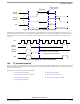
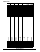
The Frequency Divide register determines the SCL or serial bit-clock frequency. Table 18-4 must be used to select FDR bits that produce an
appropriate SCL. The following relationships (1) through (4), which illustrate the connection between Table 18-4 and the signals in the I2C
timing specification, are as follows:
SCL (in kHz) = (1/1000) * [system clock speed (in Hz)] / (SCL period) (1)
SDA Hold Time (in us) = 1000 * (SDA Hold / SCL Period) / [SCL (in kHz)] (2)
SCL Hold Time of START (in us) = 1000 * (SDA Hold of START / SCL Period) / [SCL (in kHz)] (3)
SCL Hold Time of STOP (in us) = 1000 * (SDA Hold of STOP / SCL Period) / [SCL (in kHz)] (4)
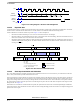
The following figure illustrates the relationship between system clock and the I2C signals.
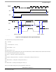
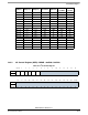
Table 18-2. I
2
C Address Register
msb 012345678 9 101112131415
R ADR[7:1]
Reserved
W
RESET:0 00000000 0 0 0 00 0 0
16 17 18 19 20 21 22 23 24 25 26 27 28 29 30 31 lsb
R
Reserved
W
RESET:0 00000000 0 0 0 00 0 0
Bit Name Description
0:6 ADR[7:1] Bits 0 to 6 contains the address I
2
C responds to, when addressed as a slave.
Note: This is not the address sent on the bus during address transfer.
7:31 — Reserved
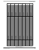
Table 18-3. I
2
C Frequency Divider Register
msb 012345678 9 101112131415
R FDR[7:0]
Reserved
W
RESET:0 00000000 0 0 0 00 0 0
16 17 18 19 20 21 22 23 24 25 26 27 28 29 30 31 lsb
R
Reserved
W
RESET:0 00000000 0 0 0 00 0 0
Bit Name Description
0:1 FDR[7:6] These 2 bits act as a prescale divider of the input module clock.
2:7 FDR[5:0] This field is used to prescale the clock for bit-rate selection.
8:31 — Reserved