
Board Users Guide


Overview
MPC5200B Users Guide, Rev. 1
Freescale Semiconductor 18-1
Chapter 18
Inter-Integrated Circuit (I
2
C)
18.1 Overview
The following sections are contained in this document:
• Section 18.2, I
2
C Controller
• Section 18.3, I
2
C Interface Registers
• Section 18.4, Initialization Sequence
• Section 18.5, Transfer Initiation and Interrupt
The Inter-Integrated Circuit (I
2
C) is a two-wire, bidirectional serial bus that provides a simple, efficient method for data exchange between
devices. This two-wire bus minimizes the interconnection between devices.
The MPC5200B contains 2 identical and independent I
2
C modules:
• I2C1 = MBAR + 0x3D00
• I2C2 = MBAR + 0x3D40
The I
2
C module is connected to the IP bus, and the CommBus.
Each module operates up to 100Kbps with a maximum bus load and timing. Both I
2
C modules are capable of operating at higher baud rates,
up to a maximum of clock/20, with reduced bus loading.
The maximum communication length and the number of devices that can be connected are limited by a maximum bus capacitance of 400pF.
This bus is suitable for applications requiring occasional communications over a short distance between a number of devices. It also provides
flexibility, allowing more devices to be connected to the bus for further expansion and system development.
I
2
C is a true multi-master bus including collision detection and arbitration to prevent data corruption if two or more masters attempt to control
the bus simultaneously. This feature provides the capability for complex applications with multi-processor control. It may also be used for
rapid testing and alignment of end products via external connections to an assembly-line computer.
18.1.1 Features
The I
2
C module has the following key features:
• Compatible with I
2
C bus standard
• Multi-master operation
• Software programmable for one of 71 different serial clock frequencies
• Software selectable acknowledge bit
• Interrupt driven Byte-by-Byte data transfer
• Arbitration loss with automatic mode switching from master to slave
• Calling address identification interrupt
• Start and stop signal generation/detection
• Repeated start signal generation
• Acknowledge bit generation/detection
• Bus busy detection
• Programmable Glitch Filter
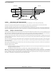
Figure 18-1 shows a block diagram of the I
2
C module.