
Board Users Guide


Programmable Serial Controller (PSC)
Notes
MPC5200B Users Guide, Rev. 1
15-70 Freescale Semiconductor
15.3.4.3 PSC in FIR Mode
The FIR mode is also a supported IrDA mode. This section will give some more informations about this mode. The important registers to
configure the PSC6 (only this PSC support the IrDA modes) for FIR mode are:
• SICR register - select the FIR mode
• MR2 register - Channel Mode
• If clock generate from the internal source:
— cdm_irda_bitclk_config - select Mclk frequency, see Section 5.5.14, PSC6 (IrDA) Mclock Config Register—MBAR + 0x0234
— cdm_clock_enable_register - enable Mclk, see Section 5.5.6, CDM Clock Enable Register—MBAR + 0x0214
— CCR- select BitClk and Frame Frequency
• IRCR1 register - full duplex and SIP mode
• IRMDR register - select the clock divider
• RFALARM, TFALARM - select the FIFO “Alarm” level
• CR register - enable or disable receiver and transmitter
• Port_config - select the right Pin-Muxing, see Chapter 2, Signal Descriptions
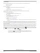
15.3.4.3.1 Block Diagram and Signal Definition for FIR Mode
The signal definition for FIR mode is the same as in SIR mode. Please see Table 15-90. Figure 15-19. shows the Block diagram for FIR mode.
The clock generation is the same as in MIR mode, see Section 15.3.4.2.1, Block Diagram and Signal Definition for MIR Mode.
15.3.4.3.2 Transmitting and Receiving in FIR Mode
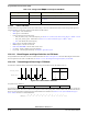
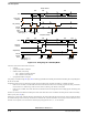
The data field is 4PPM encoded by the transmitter. Data encoding is done LSB first. Each chip duration is 125 ns.
Figure 15-21. Data Format in FIR Mode
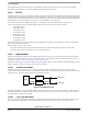
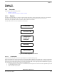
The packet format is defined as
The preamble (PA) field is used by a receiver to establish phase lock. After receiving the start flag (STA), the receiver begin to interpret the
4PPM encoded symbols. The receiver continues receiving until it receives the stop flag (STO). Like the UART mode, the FIR mode sends the
lsb first. For more informations regarding the pulse width and Baud rate calculations see Section 15.2.27, Infrared FIR Divide Register
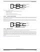
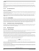
(0x54)—IRFDR. The FCS is 32 bit CRC defined as:
IMR 0xXXXX select the desired interrupt
Port_Config 0x00F00000 Select the Pin-Muxing for IrDA mode, see Chapter 2, Signal
Descriptions
CR 0x05 Enable Tx and Rx
PA STA DATA FCS STO
Table 15-92. Configuration Sequence Example for MIR Mode
Register Value Setting
binary data
0001
1011
bit pair
4PPM data
00
01
10
11
1000
0100
0010
0001
4PPM data
CRC x() x
32
x
26
x
23
x
22
x
16
x
12
x
11
x+++++++
10
x
8
x
7
x
5
x
4
x
2
x1+++++++=