
Board Users Guide


PSC Operation Modes
MPC5200B Users Guide, Rev. 1
Freescale Semiconductor 15-53
• Data shift direction SICR[SHDIR], data shifted out LSB first if SICR[SHDIR] = 1 otherwise data shifted out MSB first if
SICR[SHDIR] = 0
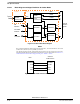
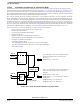
In the Codec “Soft Modem” mode the PSC send only one data word per frame.
Figure 15-9. “Soft Modem” Codec interface diagram
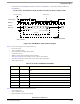
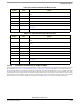
Table 15-79 shows an example how to configure the PSC1 as:
• PSC in Slave mode
• 16 bit “soft Modem” mode
• Data are sampled on the falling edge of BitClk
• FrameSync is low true
• MSB first, transfer starts with leading edge of FrameSync
• set the TFALARM level to 0x010, alarm occurs if 16 byte are in the TxFIFO
• set the RFALARM level to 0x00C, alarm occurs if 12 byte space in the RxFIFO
• enable TxRDY interrupt
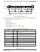
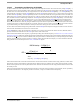
Table 15-80 shows an example how to configure the PSC2 as:
• PSC in Master mode
• 32bit “soft Modem” mode
• Data are sampled on the rising edge of BitClk
Table 15-79. 16-Bit “soft Modem“Slave Mode
Register Value Setting
CR 0x0A Disable the Tx and Rx part for configuration if the PSC was enabled by the work
before.
SICR 0x02100000 Select the 16 bit Codec mode, msb first, DTS1 = 0, slave mode
RFALARM 0x000C set the RFALARM level to 0x00C
TFALARM 0x0010 set the TFALARM level to 0x010
IMR 0x0100 enable TxRDY interrupt
Port_Config 0x00000006 Select the Pin-Muxing for PSC1 Codec mode, see Chapter 2, Signal Descriptions
CR 0x05 Enable Tx and Rx
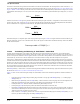
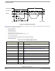
frame length
delay of time slot 1
start of Frame
Frame Sync Polarity
BitClk polarity
Frame Sync
BitCLK
DATA
data length
RX / TX
start of next Frame
frame sync width
data bit shift direction