
Board Users Guide


PSC Registers—MBAR + 0x2000, 0x2200, 0x2400, 0x2600, 0x2800, 0x2C00
MPC5200B Users Guide, Rev. 1
Freescale Semiconductor 15-33
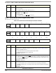
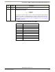
15.2.23 Infrared Control 1 (0x44)—IRCR1
This register controls the configuration in one of the IrDA modes (SIR/MIR/FIR).
15.2.24 Infrared Control 2 (0x48)—IRCR2
This register controls the configuration in one of the IrDA modes (SIR/MIR/FIR).
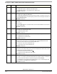
21 Disable_
EOF
UART/SIR —Disable EOF generation
0 = The UART receiver generate an EOF tag if an UART error was detected. For more
information’s regarding the UART errors (RB, FE,PE, CDE,) see register SR.
1 = The UART receiver doesn’t generate an EOF tag if an UART error was detected
other modes—Reserved
22:23 —
Reserved
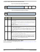
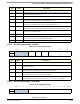
Table 15-45. Infrared Control 1 (0x44) for SIR Mode
msb 0 1 2 3 5 6 7 lsb
R
Reserved INV_RX
Reserved FD
Reserved SPUL
W
RESET: 0 0 0 0 0 0 0 0
Table 15-46. Infrared Control 1 (0x44) for MIR/FIR Modes
msb 0 1 2 3 4 5 6 7 lsb
R
Reserved
FD
SIPEN Reserved
W
RESET: 0 0 0 0 0 0 0 0
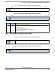
Bit Name Description
0:1 — Reserved
2INV_RXSIR / MIR / FIR—Invert the RX line
0 = The receiver doesn’t invert the receive line.
1= The receiver invert the receive line.
other Modes—Reserved
Reserved
3:4 — Reserved
5FDSIR / MIR / FIR—Full duplex enable
0 = The receiver in IrDA mode is disabled while the TX is busy.
1= The receiver in IrDA mode is not disabled while the TX is busy. This bit should not be
set in usual operations. In loop back channel mode, CM=10, this bit is automatically set.
other Modes—Reserved
6SIPENMIR / FIR—Send SIP enable after every frame
0 = SIP is sent only when the SIPREQ bit in the IRCR2 becomes high.
1 = The TX always send 1.6 µs SIP after the STO flag in order to inform slow speed de-
vices that higher speed device is connecting.
For more informations about the SIP pulse see also
Figure 15-20.
other Modes—Reserved
7 SPUL SIR—SIR pulse width
0 = SIR pulse width is 3/16 of the bit duration.
1 = SIR pulse width is 1.6 µs
other Modes—Reserved
Bit Name Description