
Board Users Guide


PSC Registers—MBAR + 0x2000, 0x2200, 0x2400, 0x2600, 0x2800, 0x2C00
MPC5200B Users Guide, Rev. 1
Freescale Semiconductor 15-7
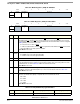
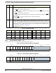
15.2.2 Mode Register 2 (0x00) — MR2
MR2 can be read or written when the Mode register pointer points to it, which occurs after any access to MR1. An MR2 access does not update
the mode register address.
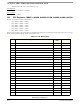
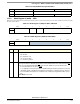
01 Force parity Low parity High parity
10 No parity n/a
11 Multidrop mode Data character Address character
Table 15-7. Mode Register 2 (0x00) for UART / SIR Mode
msb 01 234567 lsb
R CM TxRTS TxCTS SB
W
RESET:0 0 000000
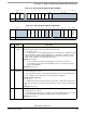
Table 15-8. Mode Register 2 (0x00) for other Modes
msb 01 234567 lsb
RCM
Reserved
W
RESET:0 0 000000
Bit Name Description
0:1 CM Channel mode—Selects a channel mode.CM is used in both UART and Codec modes.
00 = Normal
01 = Automatic echo
10 = Local loop-back
11 = Remote loop-back
2TxRTSUART / SIR—Transmitter ready-to-send—Controls negation of
RTS to automatically terminate a
message transmission. Attempting to program a receiver and transmitter in the same channel for
RTS
control is not permitted and disables RTS control for both. TxRTS is not used in Codec mode.
0 = The transmitter has no effect on
RTS.
1 = In applications where the transmitter is disabled during the last byte transmission is running
(TX FIFO is empty), setting this bit automatically clears RTS line one bit-time after any characters
in the transmitter shift registers are completely sent, including the programmed number of stop
bits.
other Modes—Reserved
Table 15-6. Parity Mode/Parity Type Definitions