
Board Users Guide


Overview
MPC5200B Users Guide, Rev. 1
Freescale Semiconductor 15-1
Chapter 15
Programmable Serial Controller (PSC)
15.1 Overview
The following sections are contained in this document:
• Section 15.2, PSC Registers—MBAR + 0x2000, 0x2200, 0x2400, 0x2600, 0x2800, 0x2C00
• Section 15.3, PSC Operation Modes
• Section 15.4, PSC FIFO System
The MPC5200 has 6 independent Programmable Serial Controllers (PSCs)
:
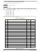
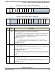
The internal configuration registers and the functional behavioral is equal for all PSC modules. Because of a Pin out limitation, not all
functions are available for all PSC’s on every ports. Table 15-1 shows, which PSC supports which mode.
.
Each PSC can be clocked by an internal clock source or an external clock source. Figure 15-2 shows a simplified PSC block diagram. In
addition, each PSC module interfaces directly to the CPU and consists of the following:
• Serial Communication Channel
• Programmable Transmit (Tx) Receive (Rx) Clock Generation
• Internal Channel Control Logic
• Interrupt Control Logic
•FIFO System
In addition the PSC provide an Mclk for the external Codec, eliminating the need for an external crystal for the external device. For more
information about the Codec mode see section: Section 15.3.2, PSC in Codec Mode
• PSC1 = MBAR + 0x2000 • PSC4 = MBAR + 0x2600
• PSC2 = MBAR + 0x2200 • PSC5 = MBAR + 0x2800
• PSC3 = MBAR + 0x2400 • PSC6 = MBAR + 0x2C00
Table 15-1. PSC Mode Overview
PSC1 PSC2 PSC3 PSC4 PSC5 PSC6
UART yes yes yes yes yes yes
Modem / SPI / I2S / ESAI yes yes yes no no yes
Mclk Generation output yes yes yes no no no
AC97 yes yes no no no no
IrDA no no no no no yes
Cell Phone master slave slave no no slave