
Board Users Guide


MPC5200B Users Guide, Rev. 1
14-2 Freescale Semiconductor
Overview
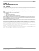
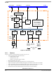
Figure 14-1. Block Diagram—FEC
14.1.1 Features
The FEC incorporates several features/design goals that are key to its use:
• Support for different Ethernet physical interfaces:
— 100 Mbps IEEE 802.3 MII
— 10 Mbps IEEE 802.3 MII
— 10 Mbps 7-wire interface (industry standard)
• IEEE 802.3 full-duplex flow control
• Programmable max frame length supports IEEE 802.1 VLAN tags and priority
• Support for full-duplex operation (200 Mbps throughput) with a minimum system clock rate of 50 MHz.
• Support for half-duplex operation (100 Mbps throughput) with a minimum system clock rate of 25 MHz.
• Large (1 Kbyte) on-chip transmit and receive FIFOs to support a variety of bus latencies.
• Retransmission from transmit FIFO following a collision (no processor bus utilization).
CSR
FIFO Controller
RISC
Controller
MII ReceiveTransmit
tbus
requests
tbus_addr
tbusd_addr
tbus_addr
MDCMDIO
RX_CLK
RX_DV
RXD[3:0]
RX_ER
TX_CLKTX_EN
TXD[3:0]
TX_ER
CRS,COL
MIB
(RISC +
microcode)
I/O
Pad
MDO
MDEN
FEC
Counters
MII/7-wire Data
Option
MDI
SIF
Bus
Controller
IP bus
T-bus
Tx FIFO (1KByte)
CLK/CNTL
CommBus Interrupt
Rx FIFO (1KByte)