
Board Users Guide


MPC5200B Users Guide, Rev. 1
12-6 Freescale Semiconductor
Host Control (HC) Operational Registers
12.4.2 Control and Status Partition—MBAR + 0x1000
This HC partition uses 6 32-bit registers. These registers are located at an offset from MBAR of 0x1000. Register addresses are relative to
this offset. Therefore, the actual register address is: MBAR + 0x1000 + register address
The following registers are available:
• USB HC Revision Register (0x1000)
• USB HC Control Register (0x1004)
• USB HC Command Status Register (0x1008)
• USB HC Interrupt Status Register (0x100C)
• USB HC Interrupt Enable Register (0x1010)
• USB HC Interrupt Disable Register (0x1014)
12.4.2.1 USB HC Revision Register—MBAR + 0x1000
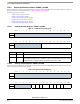
12.4.2.2 USB HC Control Register—MBAR + 0x1004
The HC Control register defines HC operating modes. Except for HostController FunctionalState and RemoteWakeUpConnected, most
fields in this register are modified only by the HCD.
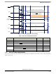
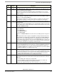
Table 12-1. USB HC Revision Register
msb 012345678 9 101112131415
R
Reserved
W
RESET:0 00000000 0 0 0 00 0 0
16 17 18 19 20 21 22 23 24 25 26 27 28 29 30 31 lsb
R
Reserved REV
W
RESET:0 00000000 0 0 1 00 0 0
Bits Name Description
0:23 – Reserved
24:31 REV Revision—a read-only field containing the BCD representation of the HCI specification
version implemented by this HC. For example, a value of 11h corresponds to version 1.1. All
HC implementations compliant with this specification have a value of 10h.
Table 12-2. USB HC Control Register
msb 012345 6 789101112131415
R
Reserved
W
RESET:0 00000 0 000 0 0 00 0 0
16 17 18 19 20 21 22 23 24 25 26 27 28 29 30 31 lsb
R
Reserved RWE RWC IR HCFS BLE CLE IE PLE CBSR
W
RESET:0 00000 0 00 0 0 0 00 0 0