
Board Users Guide


ATA Register Interface
MPC5200B Users Guide, Rev. 1
Freescale Semiconductor 11-3
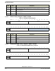
11.3.1.2 ATA Host Status Register—MBAR + 0x3A04
11.3.1.3 ATA PIO Timing 1 Register—MBAR + 0x3A08
6 IE Enables drive interrupt to pass to CPU in PIO modes.
7 IORDY Set by software when the drive supports IORDY. Required for PIO mode 3 and above.
16:31 — Reserved
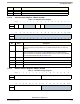
Table 11-2. ATA Host Status Register
msb 0 1 2 3 4 5 6 7 8 9 1011121314 15
R TIP UREP
Reserved RERR WERR Reserved
W
RESET:0 0 0000 0 0 0000000 0
16 17 18 19 20 21 22 23 24 25 26 27 28 29 30 31 lsb
R
Reserved
W
RESET:0 0 0000 0 0 0000000 0
Bits Name Description
0 TIP Transaction in Progress—indicator bit MUST be polled by software before PIO access.
System bus (XL bus) locks up if PIO access is attempted while this bit is set. This bit is
read-only.
1 UREP UDMA Read Extended Pause—bit sets when drive stops strobing for an extended period
without initiating burst termination by negating DMARQ, during an UDMA read burst.
Software may initiate an Ultra DMA read burst termination, in this case by setting ATA Drive
Device Command Register HUT bit (see Table 11-29.).
2:5 — Reserved
6 RERR Read Error—An un-implemented register read.
7 WERR Write Error—An un-implemented register write.
8:31 — Reserved
Table 11-3. ATA PIO Timing 1 Register
msb 012345678 9 101112131415
R pio_t0 pio_t2_8
W
RESET:0 00000000 0 0 0 00 0 0
16 17 18 19 20 21 22 23 24 25 26 27 28 29 30 31 lsb
R pio_t2_16
Reserved
W
RESET:0 00000000 0 0 0 00 0 0
Bits Name Description