
Board Users Guide


Real-Time Clock
MPC5200B Users Guide, Rev. 1
Freescale Semiconductor 7-65
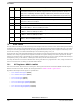
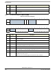
7.5.1.4 SLT 0 Timer Status Register—MBAR + 0x070C
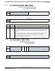
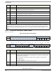
SLT 1 Timer Status Register—MBAR + 0x071C
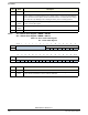
7.6 Real-Time Clock
The Real-Time Clock (RTC) uses an external 32KHz crystal to provide:
•alarm
• stop-watch
• periodic interrupts
— minute
— second
— midnight rollover(day)
The clock runs as long as power is maintained and the crystal is running, regardless of MPC5200B power-down states.
The RTC module has the following features:
• full clock features
• minute countdown timer—provides 256-minute capability, slightly over 4 hours
• programmable alarm—operates on time of day only, not related to calendar
• periodic interrupts for:
— 1 second
— 1 minute
— 1 day—operates only at midnight rollover
• calendar features:
—day
—date
—year
• Crystal support (32.768KHz only)
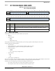
RTC registers are writable, letting time and date be updated. If software enabled, RTC operates during all MPC5200B power-down modes.
At a reset , control registers are put in a default state such that no interrupts generate until software enabled.
The RTC has two CPU interrupt signals connected to the Interrupt Controller, they are:
• RTC_Periodic, which is Main Level 5 fed by the Day, Minute, or Second sources.
• RTC_Stopwatch, which is Main Level 6 fed by the Alarm or Stopwatch sources.
Table 7-54. SLT 0 Timer Status Register
SLT 1 Timer Status Register
msb 012345678 9 101112131415
R Reserved ST Reserved
W
RESET:0 00000000 0 0 0 00 0 0
16 17 18 19 20 21 22 23 24 25 26 27 28 29 30 31 lsb
R
Reserved
W
RESET:0 00000000 0 0 0 00 0 0
Bit Name Description
0:6 — Reserved
7 ST This status bit goes high whenever the Timer has reached Terminal Count. The bit is cleared by
writing 1 to its bit position. If Interrupts are enabled, clearing this status bit also clears the
interrupt.
8:31 — Reserved