
Board Users Guide


Interrupt Controller
MPC5200B Users Guide, Rev. 1
Freescale Semiconductor 7-7
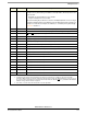
7.2.4.2 ICTL Peripheral Priority and HI/LO Select 1 Register —MBAR + 0x0504
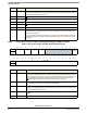
Table 7-5. ICTL Peripheral Priority and HI/LO Select 1 Register
msb 012345678 9 101112131415
R Per0_pri Per1_pri Per2_pri Per3_pri
W
RESET:0 00000000 0 0 0 00 0 0
16 17 18 19 20 21 22 23 24 25 26 27 28 29 30 31 lsb
R Per4_pri Per5_pri Per6_pri Per7_pri
W
RESET:0 00000000 0 0 0 00 0 0
Bits Name Description
— Per[x]_pri Priority encoding is done using 4 configuration bits per input source. Each group of 4bits
controls the source priority in relation to other peripheral sources. The most significant bit
(msb) of each config nibble is called the HI/LO or "bank" bit.
If this bit is high it implies not only a high priority, but causes this interrupt source to assert a
HI interrupt condition. Under most circumstances this creates a Critical Interrupt assertion to
the e300 core. See Note 1.
Peripherals with identical priority settings (either zero or non-zero) are default prioritized with
"lower peripheral has higher priority". In other words, Per1 has a default priority higher than
Per2.
0:3 Per0_pri Peripheral 0 = BestComm interrupt (fixed as highest peripheral)
4:7 Per1_pri Peripheral 1 = PSC1 interrupt source
8:11 Per2_pri Peripheral 2 = PSC2
12:15 Per3_pri Peripheral 3 = PSC3
16:19 Per4_pri Peripheral 4 = PSC6
20:23 Per5_pri Peripheral 5 = Ethernet
24:27 Per6_pri Peripheral 6 = USB
28:31 Per7_pri Peripheral 7 = ATA
Note:
1. Per0_pri, associated with the BestComm interrupt source, is not programmable and always has the highest peripheral
priority and always results in a HI interrupt condition to the Interrupt Controller. These bits are writable and readable, but
have no effect on controller operation.