
Circuit Board Reference Manual
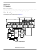

Memory Map/Register Definition
MCF548x Reference Manual, Rev. 3
Freescale Semiconductor 28-5
28.3.2.3 I
2
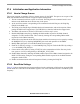
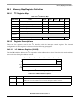
C Control Register (I2CR)
The I2CR is used to enable the I
2
C module and the I
2
C interrupt. It also contains bits that govern operation
as a slave or a master.
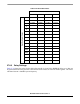
28.3.2.4 I
2
C Status Register (I2SR)
This I2SR contains bits that indicate transaction direction and status.
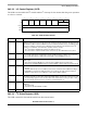
76543210
R IEN IIEN MSTA MTX TXAK RSTA 0 0
W
Reset00000000
Reg
Addr
MBAR + 0x8F08
Figure 28-4. I
2
C Control Register (I2CR)
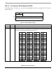
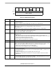
Table 28-5. I2CR Field Descriptions
Bits Name Description
7IENI
2
C enable. Controls the software reset of the entire I
2
C module. If the module is enabled in the
middle of a byte transfer, slave mode ignores the current bus transfer and starts operating when the
next START condition is detected. Master mode is not aware that the bus is busy; so initiating a start
cycle may corrupt the current bus cycle, ultimately causing either the current master or the I
2
C
module to lose arbitration, after which bus operation returns to normal.
0 The I
2
C module is disabled, but registers can still be accessed.
1 The I
2
C module is enabled. This bit must be set before any other I2CR bits have any effect.
6IIEN I
2
C interrupt enable.
0 I
2
C module interrupts are disabled, but currently pending interrupt conditions are not cleared.
1 I
2
C module interrupts are enabled. An I
2
C interrupt occurs if I2SR[IIF] is also set.
5 MSTA Master/slave mode select bit. If the master loses arbitration, MSTA is cleared without generating a
STOP signal.
0 Slave mode. Changing MSTA from 1 to 0 generates a STOP and selects slave mode.
1 Master mode. Changing MSTA from 0 to 1 signals a START on the bus and selects master mode.
4 MTX Transmit/receive mode select bit. Selects the direction of master and slave transfers.
0 Receive
1 Transmit. When the processor is addressed as a slave, software should set MTX according to
I2SR[SRW]. In master mode, MTX should be set according to the type of transfer required.
Therefore, when the processor addresses a slave device, MTX is always 1.
3 TXAK Transmit acknowledge enable. Specifies the value driven onto SDA during acknowledge cycles for
both master and slave receivers. Note that writing TXAK applies only when the I
2
C bus is a receiver.
0 An acknowledge signal is sent to the bus at the ninth clock bit after receiving one byte of data.
1 No acknowledge signal response is sent (that is, acknowledge bit = 1).
2 RSTA Repeat start. Always read as 0. Attempting a repeat start without bus mastership causes loss of
arbitration.
0 No repeat start
1 Generates a repeated START condition.
1–0 — Reserved, should be cleared.