
Circuit Board Reference Manual

Memory Map/Register Definition
MCF548x Reference Manual, Rev. 3
Freescale Semiconductor 28-3
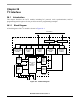
28.3 Memory Map/Register Definition
28.3.1 I
2
C Register Map
.
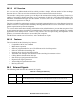
28.3.2 Register Descriptions
There are five registers used in the I
2
C interface with the interrupt control register. The internal
configuration of these registers is discussed in the following paragraphs.
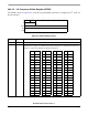
28.3.2.1 I
2
C Address Register (I2ADR)
The I2ADR holds the address the I
2
C responds to when addressed as a slave. Note that it is not the address
sent on the bus during the address transfer.
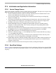
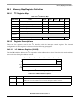
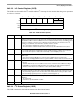
Table 28-2. I
2
C Memory Map
MBAR Offset Name Byte0 Byte1 Byte2 Byte3 Access
0x8F00 I
2
C Address Register I2ADR — R/W
0x8F04 I
2
C Frequency Divider Register I2FDR — R/W
0x8F08 I
2
C Control Register I2CR — R/W
0x8F0C I
2
C Status Register I2SR — R/W
0x8F10 I
2
C Data I/O Register I2DR — R/W
0x8F14 –
0x8F1C
Reserved
0x8F20 I
2
C Interrupt Control Register I2ICR — R/W
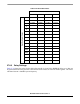
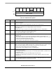
76543210
RADR 0
W
Reset00000000
Reg
Addr
MBAR + 0x8F00
Figure 28-2. I
2
C Address Register (I2ADR)
Table 28-3. I2ADR Field Descriptions
Bits Name Description
7–1 ADR Slave address. Contains the specific slave address to be used by the I2C module.
Note: This is not the address sent on the bus during the address transfer.
0 — Reserved, should be cleared.